Liquid ejection device

a liquid ejection device and liquid ejection technology, applied in printing, other printing apparatus, etc., can solve the problem of localized color unevenness in images printed on paper, and achieve the effect of reliable generation of bending deformation

Inactive Publication Date: 2014-07-15
SEIKO EPSON CORP
View PDF36 Cites 1 Cited by
  • Summary
  • Abstract
  • Description
  • Claims
  • Application Information

AI Technical Summary

Benefits of technology

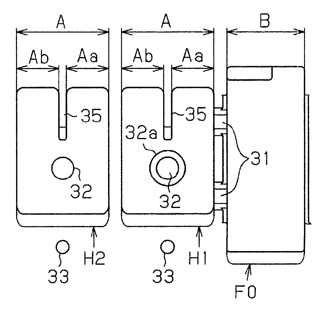
[0009]In such a case, with wide width paper support by suction on the medium support unit, though the bending deformation of the paper that occurs in the width direction is smaller at the positions corresponding to the recesses, it can easily become bigger at positions corresponding to the narrow width ink discarding grooves. Also, for example when the paper is swollen due to adhesion of ink ejected from the liquid ejection head during printing, though the bending deformation in the width direction of the paper that accompanies this swelling is also smaller at the recesses, it easily becomes larger at the narrow width ink discarding grooves. Therefore, with the suctioned paper, the bending is concentrated at the larger width ink discarding grooves, and greater bending of the paper occurs more easily at the ink discarding grooves than at the recesses. Because of that, the paper supported on the medium support unit has little bending at the recesses, so the impact displacement volume is small, and the bending at the ink discarding grooves is great, so the impact displacement volume is great. As a result, for example, there is the problem that localized color unevenness occurs in images printed on the paper.
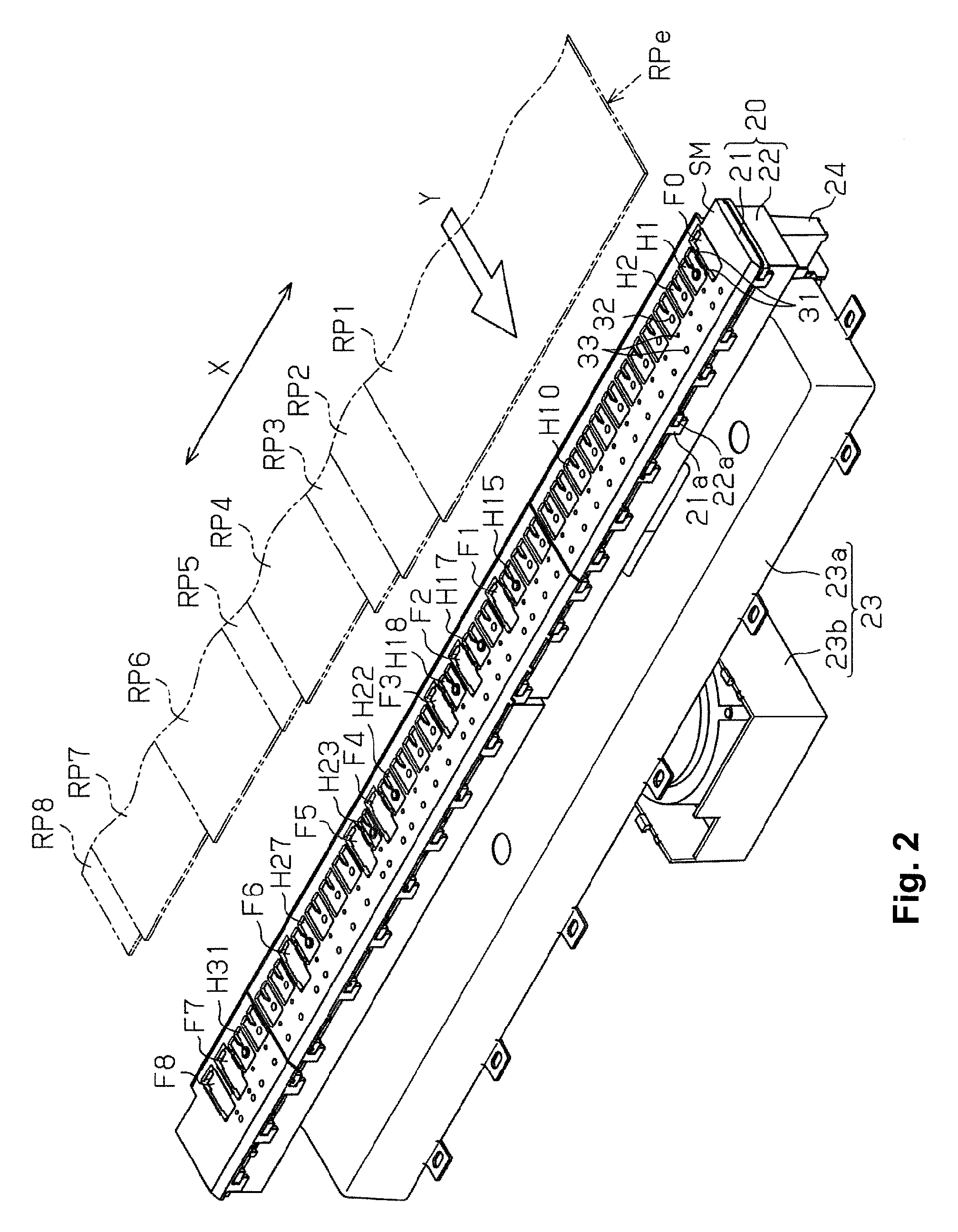
[0014]With this arrangement, at the upstream side of the transport direction of the medium support surface at which suction of the ejection medium is started, it is possible to suppress bending deformation of the ejection medium at the first recesses that occurs in the width direction orthogonal to the transport direction by using the ribs. As a result, at the first recesses, since it is supported on the medium support surface suctioned in a state with bending deformation suppressed, the ejection medium is supported at a suitable position on the medium support surface.
[0016]With this arrangement, the liquid ejected from the liquid ejection head can be accepted with high reliability at the second recesses. Therefore, soiling of the medium support surface by the liquid is suppressed.
[0020]With this arrangement, negative pressure is imparted to the first recess via the suction hole provided in the first recess, so it is possible to reliably generate bending deformation on the ejection medium at the first recess.

Problems solved by technology

As a result, for example, there is the problem that localized color unevenness occurs in images printed on the paper.

Method used


Image

  • Liquid ejection device
  • Liquid ejection device
  • Liquid ejection device

Examples


Embodiment Construction

[0028]Following, as an embodiment with the present invention in a specific example, we will describe an inkjet printer (hereafter referred to simply as “printer”) as an example of a liquid ejection device, equipped with a liquid ejection head for ejecting liquid, for forming (printing) an image or the like containing text or graphics by ejecting liquid on paper (roll paper) as an ejection medium, while referring to the drawings.

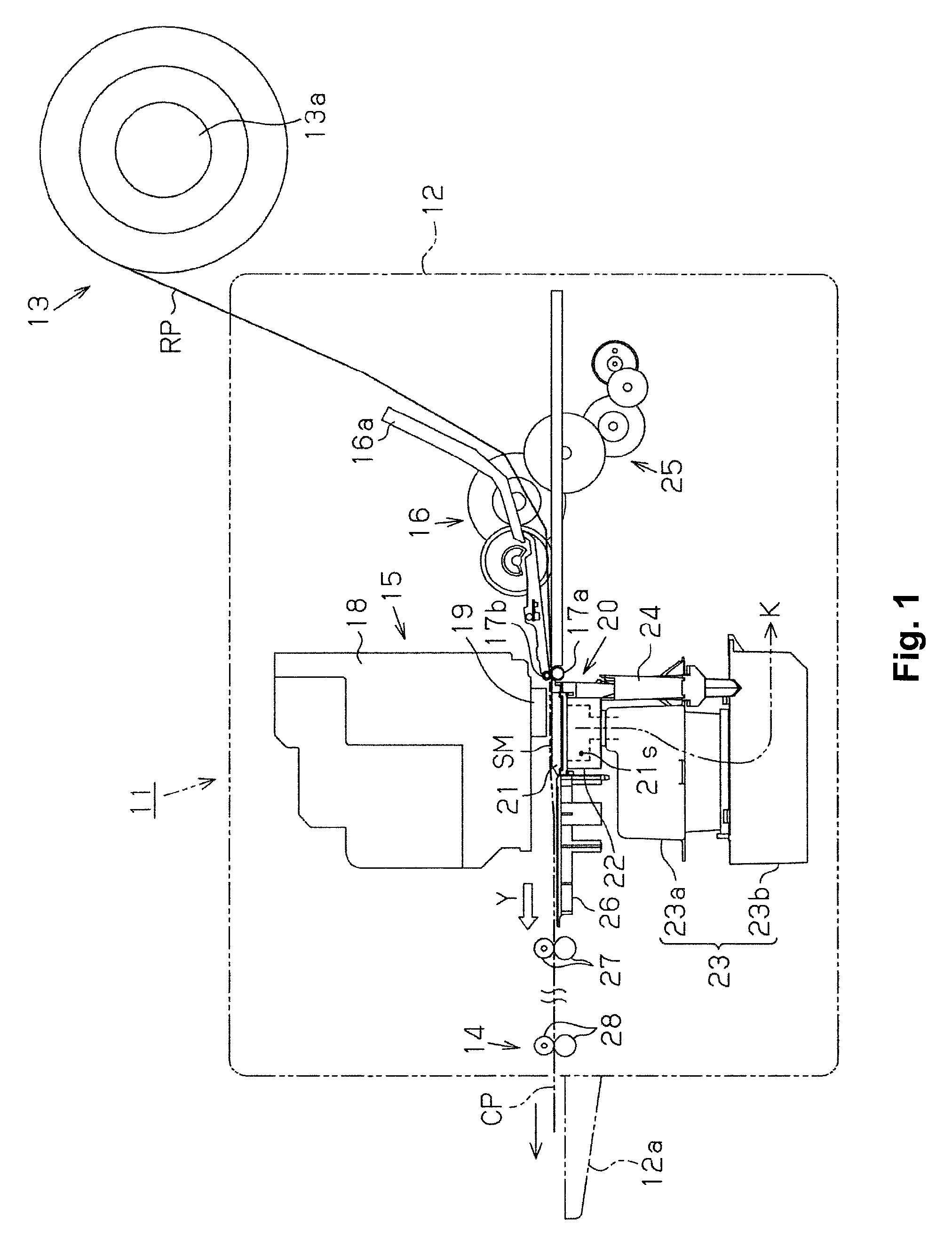
[0029]As shown in FIG. 1, the printer 11 has a main unit case 12, and a paper supply unit 13 with the long sheet form paper RP supplied to the main unit case 12 equipped in a rolled state wound onto a roll shaft 13a. Equipped inside the main unit case 12 are a liquid ejection unit 15 that ejects liquid on the supplied paper RP to form an image or the like, and a paper ejection unit 14 for ejecting from a paper ejection port provided on the main unit case 12 to a paper ejection tray 12a the paper RP on which an image or the like is formed as cut paper CP.

[0030...


PUM


Abstract

A liquid ejection device includes a transport unit, a medium support unit and a liquid ejection head. The medium support unit includes a plurality of first recesses and a plurality of second recesses arranged on a medium support surface along a width direction orthogonal to a transport direction. The first and second recesses are configured and arranged to be imparted with negative pressure. A width dimension of an opening of the first recess in the width direction is larger on the downstream side than on an upstream side. A width dimension of an opening of the second recess in the width direction is smaller than the width dimension of the opening of the first recess in the width direction on the downstream side with respect to the transport direction. The second recesses are configured and arranged to accept the liquid ejected toward the ejection medium from the liquid ejection head.

Description

CROSS-REFERENCE TO RELATED APPLICATIONS[0001]This application claims priority to Japanese Patent Application No. 2012-026451 filed on Feb. 9, 2012. The entire disclosure of Japanese Patent Application No. 2012-026451 is hereby incorporated herein by reference.BACKGROUND[0002]1. Technical Field[0003]The present invention relates to a liquid ejection device for ejecting a liquid on an ejection medium that is supported by suction on a medium support unit.[0004]2. Related Art[0005]From the past, inkjet printers (hereafter referred to simply as “printers”) have been put to practical use as liquid ejection devices for ejecting ink as a liquid from a liquid ejection head onto paper (ejection medium) in a sheet form supported on a medium support unit, and forming an image containing text or graphics. Among this type of printer, there is a printer that performs so-called “borderless printing” which ejects ink from the liquid ejection head on the entire surface of the paper to form an image.[...

Claims


Application Information

Patent Timeline
Patent Type & Authority Patents(United States)
IPC IPC(8): B41J2/01B41J11/00
CPCB41J11/0085B41J11/0045B41J11/06B41J13/0009
Inventor YAMAMOTO, TAKAOYOSHIDA, HIROTAKA
Owner SEIKO EPSON CORP
Why Eureka
Try Eureka