Control device for vehicular continuously variable transmission

Active Publication Date: 2014-12-04
TOYOTA JIDOSHA KK
View PDF1 Cites 0 Cited by
  • Summary
  • Abstract
  • Description
  • Claims
  • Application Information

AI Technical Summary

Benefits of technology

The invention relates to a control device for a continuously variable transmission in a vehicle. The technical effects of the invention include cancelling out individual variation in the continuously variable transmission during vehicle deceleration running, ensuring proper gear ratio cancellation and starting performance at the next vehicle stop, and improving drivability and starting performance while ensuring proper gear ratio cancellation and starting performance during vehicle deceleration running.

Problems solved by technology

Therefore, if a shift to “N” is made during running, the transmission input rotation speed becomes unable to be detected and the shift control of the continuously variable transmission cannot be provided through the FB control, resulting in the shift control of the continuously variable transmission provided only through the FF control.
As a result, since the gear ratio of the continuously variable transmission is not completely returned to the Lowest at the time of the vehicle stop, vehicle starting performance may deteriorate.
Such a problem is unknown and no proposal has hitherto been made on properly changing a gear ratio to the lower vehicle speed side during vehicle deceleration even when the shift control of the continuously variable transmission is provided only through the FF control.

Method used


Image

  • Control device for vehicular continuously variable transmission
  • Control device for vehicular continuously variable transmission
  • Control device for vehicular continuously variable transmission

Examples


example

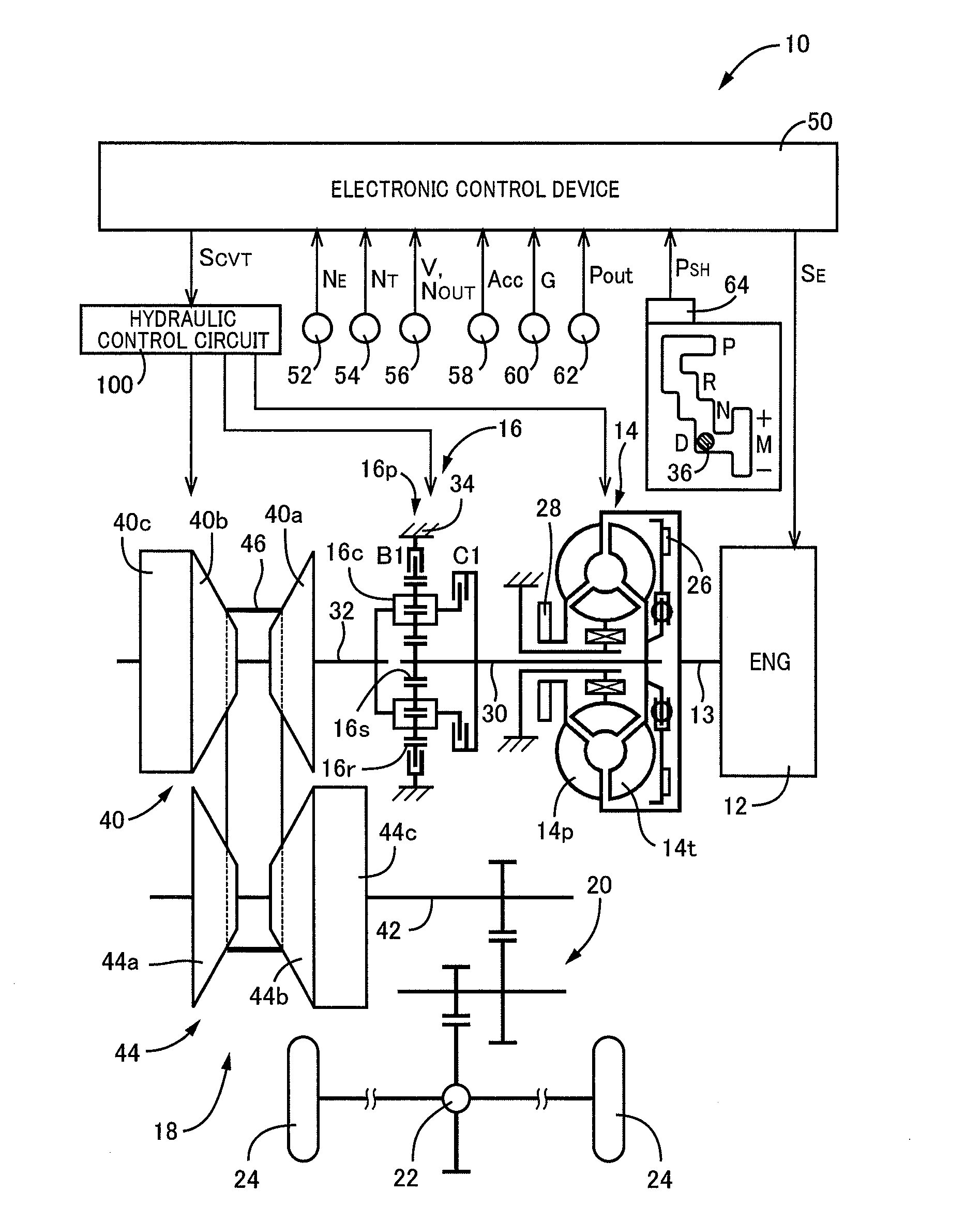
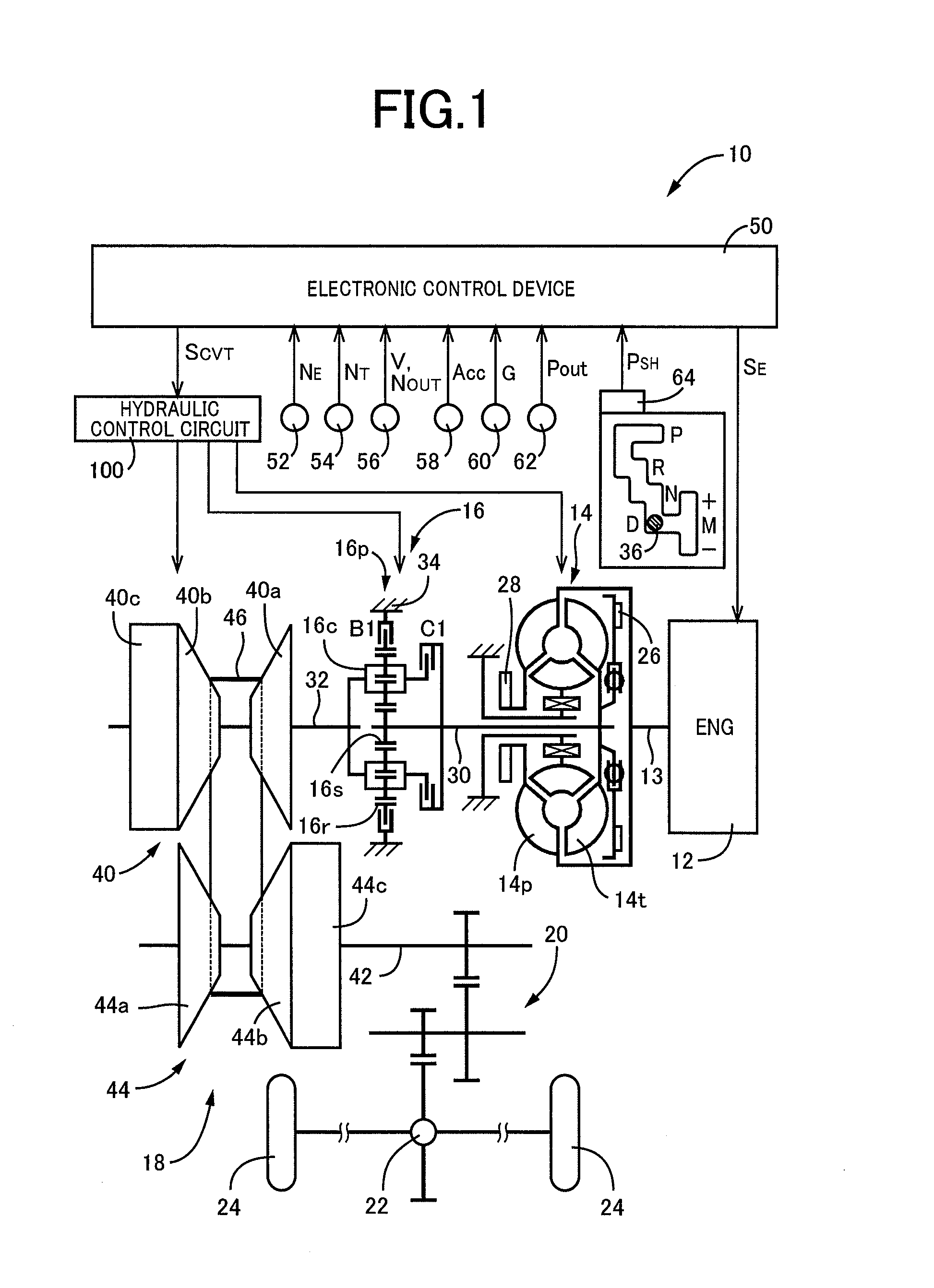
[0029]FIG. 1 is a diagram for explaining a general configuration of a vehicle 10 to which the present invention is applied and is a block diagram for explaining a main portion of a control system disposed for controlling portions of the vehicle 10. In FIG. 1, power output from an engine 12 acting as a drive force source for running is transmitted sequentially through a torque converter 14 acting as a fluid transmission device (hydraulic power transmission device), a forward / reverse switching device 16 acting as a transmission path connecting / disconnecting device, a belt type continuously variable transmission (hereinafter referred to as a continuously variable transmission (CVT)) 18 acting as a continuously variable transmission for a vehicle, a reduction gear device 20, a differential gear device 22, etc., to left and right drive wheels 24.

[0030]The torque converter 14 includes a pump impeller 14p coupled to a crankshaft 13 of the engine 12 and a turbine impeller 14t coupled to the...


PUM


Abstract

A control device of a continuously variable transmission for a vehicle to which power of a drive force source is input through a transmission path connecting / disconnecting device changes a gear ratio of the continuously variable transmission to a lower vehicle speed side during vehicle deceleration when the transmission path connecting / disconnecting device is in a power transmission interrupted state of interrupting power transmission through a power transmission path between the drive force source and the continuously variable transmission, earlier as compared to when the transmission path connecting / disconnecting device is in a power transmittable state enabling the power transmission, and the control device changes a gear ratio of the continuously variable transmission earlier to the lower vehicle speed side when vehicle deceleration is larger, when the transmission path connecting / disconnecting device is in the power transmission interrupted state.

Description

TECHNICAL FIELD[0001]The present invention relates to a control device of a continuously variable transmission for a vehicle to which power of a drive force source is input via a transmission path connecting / disconnecting device.BACKGROUND ART[0002]A continuously variable transmission such as a belt-type continuously variable transmission and a toroidal-type continuously variable transmission is well known. For example, this corresponds to continuously variable transmissions described in Patent Documents 1 and 2. Such a continuously variable transmission uses, for example, a rotation speed on an input side of the continuously variable transmission (transmission input rotation speed), a gear ratio of the continuously variable transmission based on the transmission input rotation speed and a rotation speed on an output side of the continuously variable transmission (transmission output rotation speed) and the like to provide shift control of the continuously variable transmission thro...

Claims


Application Information

Patent Timeline
IPC IPC(8): B60W10/101B60W10/02
CPCB60W10/02B60W10/101F16H61/0204F16H2061/0234F16H2061/6605B60Y2300/18083F16H61/66259B60W2520/105B60W2710/1005B60W2510/0208
Inventor ISHIKAWA, SHUHEIKIMURA, MOTONORIAYABE, ATSUSHITOYODA, SHINYA
Owner TOYOTA JIDOSHA KK
Why Eureka
Try Eureka