Virtual object display device, method, program, and system

a virtual object and display device technology, applied in the field of virtual object display devices, can solve the problems of difficult to perform an operation for moving an image, such as a finger, and become more difficult to perform an operation for moving a finger or the like, and achieve the effect of accurately changing the display state of the virtual obj

Active Publication Date: 2019-07-23
FUJIFILM CORP
View PDF27 Cites 2 Cited by
  • Summary
  • Abstract
  • Description
  • Claims
  • Application Information

AI Technical Summary

Benefits of technology

[0012]The present invention has been made in view of the above-described circumstances, and the object of the present invention is to make it possible to change the display state of a virtual object with high accuracy.
[0038]According to the present invention, a virtual object is displayed based on the display information, and the change information for changing the display state of the virtual object is acquired according to the relative relationship between the reference marker image showing a reference marker as a reference and each of other marker images showing other markers other than the reference marker, among a plurality of marker images that show a plurality of markers for changing the display state of the virtual object and that are included in the background image. Then, the display state of the virtual object is changed according to the change information. Therefore, by simply changing the relative relationship between the reference marker and each of the other markers, it is possible to change the display state of the virtual object. As a result, it is possible to accurately change the display state of the virtual object according to the actual operation.

Problems solved by technology

For this reason, if the position of the displayed virtual object changes due to a change in the direction of the face of the operator or the like, it becomes difficult to perform an operation for moving an image, such as a finger.
Accordingly, it becomes more difficult to perform an operation for moving a finger or the like.
For this reason, there is no real feeling, such as pressing a button, and it is difficult to perform an operation for minutely changing the display state.
In this case, however, it is necessary to separately prepare hardware, and a complicated application for changing the display state of a virtual object using the hardware is required.
However, as in the methods disclosed in JP2011-198150A and JP2013-105330A, if the position of the displayed virtual object changes due to a change in the direction of the face of the operator or the like, it becomes difficult to perform an operation for change.
In addition, it is difficult to perform an operation for minutely changing the display state of the virtual object.

Method used


Image

  • Virtual object display device, method, program, and system
  • Virtual object display device, method, program, and system
  • Virtual object display device, method, program, and system

Examples


Embodiment Construction

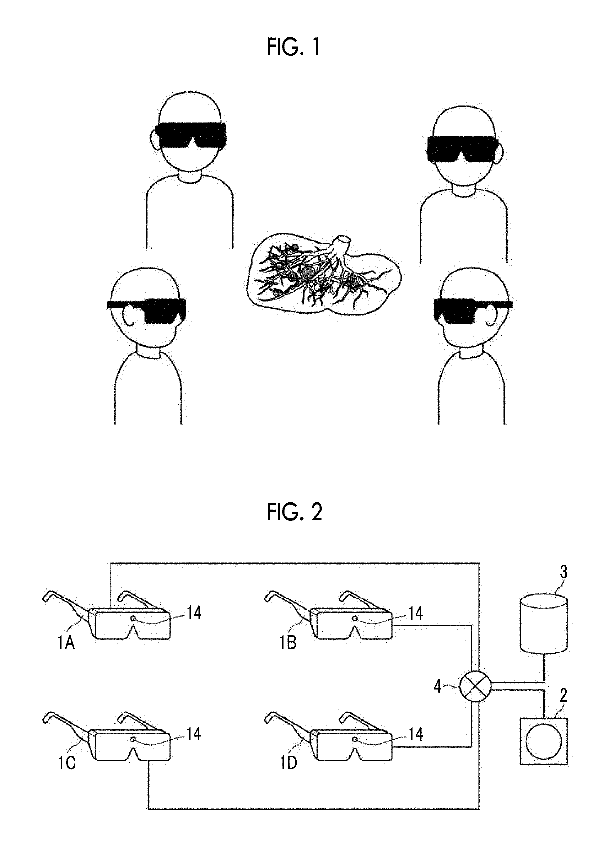
[0057]Hereinafter, embodiments of the present invention will be described with reference to the diagrams. FIG. 1 is a diagram illustrating how a virtual object display device according to a first embodiment of the present invention is used. The virtual object display device according to the first embodiment is for displaying a three-dimensional image of the liver, which is a surgery target, as a virtual object using augmented reality in a preoperative conference. Specifically, the virtual object display device according to the first embodiment is used in a situation where a three-dimensional image of the liver is generated as a virtual object from a three-dimensional image obtained by imaging a subject, each attendee of surgery wears a head mount display (hereinafter, referred to as an HMD) in a preoperative conference, and a virtual object is displayed on the HMD to receive various surgical explanations regarding the surgery from a lead surgeon who is the representative of the preo...


PUM


Abstract

A camera 14 acquires a background image B0, and a virtual object acquisition unit 22 acquires a virtual object S0. A display information acquisition unit 23 acquires display information indicating a position, at which the virtual object S0 is displayed, from the background image B0, and a display control unit 24 displays the virtual object S0 on a display 15 based on the display information. A change information acquisition unit 25 acquires change information for changing the display state of the virtual object S0 according to the relative relationship between a reference marker image 36 and each of the other marker images 37, among a plurality of marker images 36 and 37 for changing the display state of the virtual object S0 that are included in the background image B0. A display state change unit 26 changes the display state of the virtual object according to the change information.

Description

CROSS-REFERENCE TO RELATED APPLICATIONS[0001]This application is a Continuation of PCT International Application No. PCT / JP2016 / 051871 filed on Jan. 22, 2016, which claims priority under 35 U.S.C § 119(a) to Patent Application No. 2015-027390 filed in Japan on Feb. 16, 2015, all of which are hereby expressly incorporated by reference into the present application.BACKGROUND OF THE INVENTION[0002]1. Field of the Invention[0003]The present invention relates to a virtual object display device, method, non-transitory computer readable recording medium storing a program, and system capable of changing the display state of a virtual object when displaying the virtual object using augmented reality, for example.[0004]2. Description of the Related Art[0005]In recent years, a display system has been proposed that uses augmented reality that makes a virtual object appear as if it is present in real space by superimposing the virtual object on a real-time background image obtained by imaging th...

Claims


Application Information

Patent Timeline
Patent Type & Authority Patents(United States)
IPC IPC(8): G06F3/0484G06T19/20G06T19/00G02B27/01G06F3/01G06F3/0481G16H40/63G16H20/40A61B90/20G06F3/048
CPCG06F3/0484G02B27/0172G06F3/011G06F3/014G06F3/04817G06T19/006G06T19/20G16H20/40G16H40/63A61B90/20G06T2219/2024G02B2027/0141G02B2027/0178G06F2203/04802G06T2219/2012A61B2090/502A61B2034/105A61B2090/365A61B2090/368
Inventor MASUMOTO, JUN
Owner FUJIFILM CORP
Why Eureka
Try Eureka