Liquid crystal optical element, optical device, and aperture control method

a technology of liquid crystal optical elements and aperture control methods, applied in the direction of instruments, lenses, record information storage, etc., can solve the problems of reducing the number of light sources, increasing cost and yield, and difficult to provide for a plurality of light wavelengths, so as to accurately change the numerical aperture of the objective lens regardless

Inactive Publication Date: 2015-01-06
CITIZEN WATCH CO LTD
View PDF20 Cites 2 Cited by
  • Summary
  • Abstract
  • Description
  • Claims
  • Application Information

AI Technical Summary

Benefits of technology

[0011]It is an object of the present invention to provide a liquid crystal optical element that can accurately change the numerical aperture of the objective lens regardless of variations in temperature or wavelength.
[0012]It is another object of the present invention to provide a liquid crystal optical element that can accurately change the numerical aperture of the objective lens by using a simple structure.
[0013]It is a further object of the present invention to provide a liquid crystal optical element that can accurately change the numerical aperture of the objective lens without causing interference, due to unwanted light, when the numerical aperture is limited.
[0017]According to the present invention, the aperture control can be effectively performed by using the liquid crystal optical element but without using any movable parts.

Problems solved by technology

However, since it is not easy to form a ring belt for causing interference to a particular wavelength on the objective lens, this prior art design has had the problem of increased cost and reduced yield.
A further problem has been that it is difficult to provide for a plurality of light wavelengths because the wavelength for which the interference action can be effectively caused is limited to a particular wavelength.
To eliminate the unwanted light, the polarization beam splitter must invariably be inserted in the light path, but the problem has been that, because of the provision of the polarization beam splitter, the amount of light decreases or the freedom of design of the light path is limited.
There has also been the problem that the polarization beam splitter is expensive, correspondingly increasing the cost of the device.
However, since the refractive index of the liquid crystal changes with temperature, there has been the problem that a strict temperature control mechanism becomes necessary in order to accurately operate the liquid crystal panel as a λ / 4 panel and, as a result, the complexity of the structure increases correspondingly.
Furthermore, as the refractive index of the liquid crystal changes with wavelength, there has also been the problem that light of a plurality of wavelengths cannot be used.
A further problem has been that light that has not been accurately rotated through λ / 4 is directed back to the light detector as noise.
However, as the wavelength-selective diffraction gratings arranged at precisely equally spaced intervals are not easy to fabricate because of their geometry, this prior art device has had the problem of increased cost and reduced yield.
Furthermore, the wavelength that can be effectively diffracted is limited to a particular wavelength, but this wavelength varies with the temperature of the light source; therefore, there has been the problem that a strict temperature control mechanism becomes necessary in order to effectively achieve diffraction and, as a result, the complexity of the structure is correspondingly increased.

Method used


Image

  • Liquid crystal optical element, optical device, and aperture control method
  • Liquid crystal optical element, optical device, and aperture control method
  • Liquid crystal optical element, optical device, and aperture control method

Examples


Embodiment Construction

[0029]A liquid crystal optical element, an optical device, and an aperture control method according to the present invention will be described below with reference to the drawings. It should, however, be understood that the present invention is not limited to the embodiments shown in the drawings.

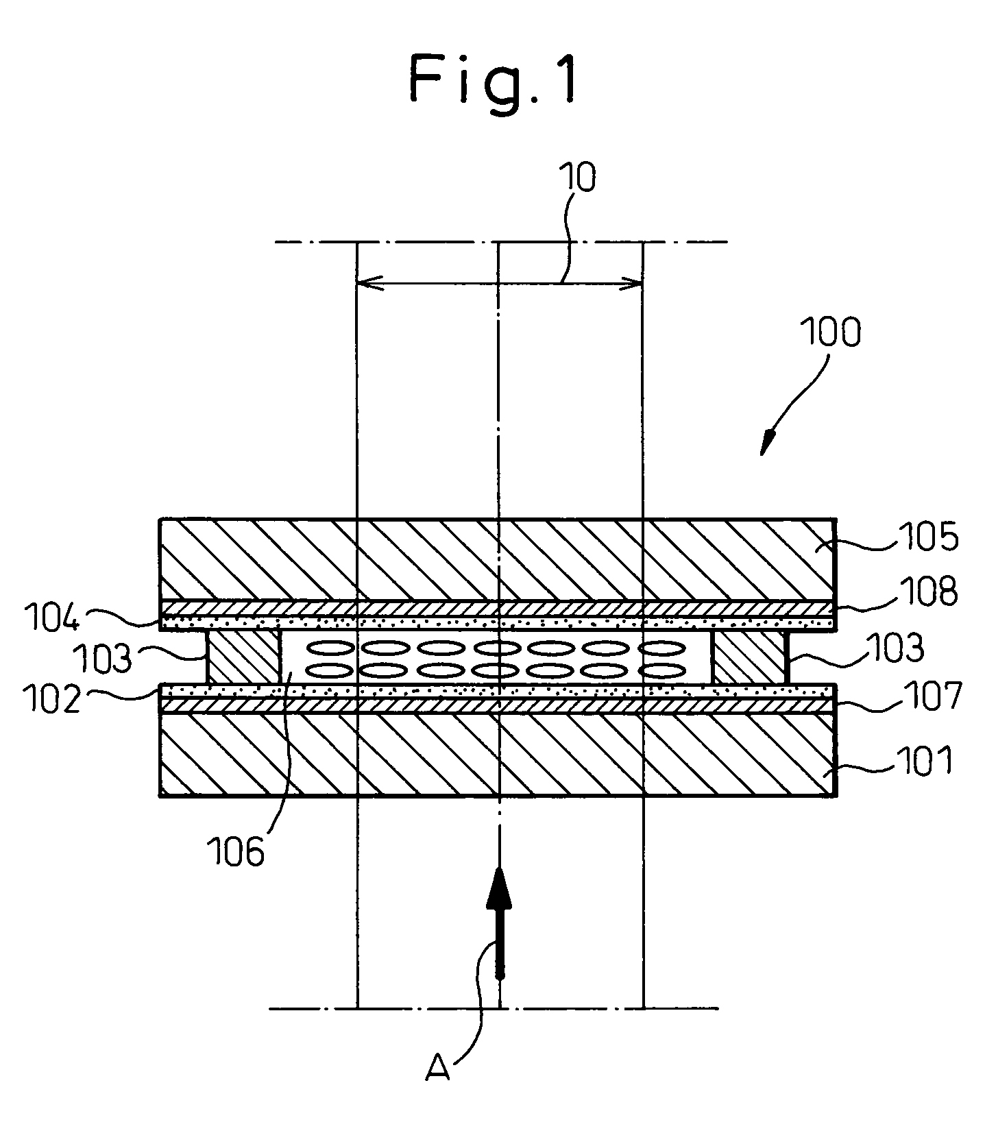
[0030]FIG. 1 is a diagram showing a cross-sectional view of the liquid crystal optical element 100 according to the present invention.

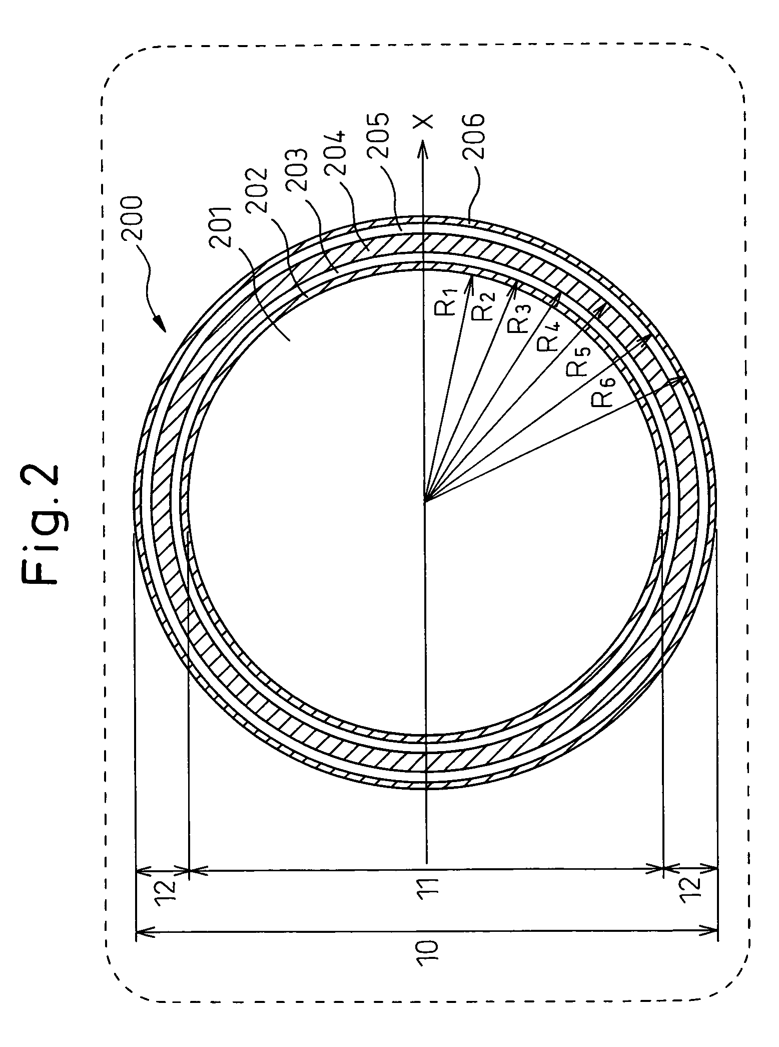
[0031]The direction shown by arrow A in the figure indicates the direction from which light is incident on the liquid crystal optical element 100. In FIG. 1, an alignment film 102 and a transparent electrode having a refractive index correcting transparent electrode pattern 200 to be described hereinafter are formed on a transparent substrate 101 on the light incident side. On the other hand, an alignment film 104 and a transparent counter electrode 108 are formed on a transparent substrate 105 on the opposite side. A liquid crystal 106, about 10 μm thick, is...


PUM

PropertyMeasurementUnit
thickaaaaaaaaaa
thickaaaaaaaaaa
RMS voltageaaaaaaaaaa

Abstract

The present invention is directed to the provision of a liquid crystal optical element that can accurately change the numerical aperture of an objective lens regardless of variations in temperature or wavelength. The liquid crystal optical element comprises a first substrate, a second substrate, a liquid crystal provided between the first and second substrates, an electrode pattern formed on one of the first and second substrates and having an aperture control region, and an opposite electrode formed on the other one of the first and second substrates, the opposite electrode being opposed to the electrode pattern for applying a voltage therebetween, wherein a plurality of electrodes, for changing refractive index and thereby causing the incident light passing through the aperture control region to diverge, are formed in the aperture control region.

Description

[0001]This application is a new U.S. patent application that claims benefit from JP 2005-125239 filed on Apr. 22, 2005. The entire content of JP 2005-125239 is herein incorporated by reference.TECHNICAL FIELD[0002]The present invention relates to a liquid crystal optical element for controlling the aperture of a light beam, an optical device using such a liquid crystal optical element, and an aperture control method for use in such an optical device.BACKGROUND OF THE INVENTION[0003]An optical pickup device that is designed to be able to read optical recording media of different numerical aperture specifications, such as CD and DVD, by adding a ring belt to an objective lens and thereby apparently causing the light falling on the outer edges to vanish for a given wavelength by the interference action of the ring (Patent Document 1), is known. However, since it is not easy to form a ring belt for causing interference to a particular wavelength on the objective lens, this prior art des...

Claims


Application Information

Patent Timeline
Patent Type & Authority Patents(United States)
IPC IPC(8): G02F1/1343G11B7/139G11B7/1392G11B7/1369G02F1/29G11B7/00G11B7/135
CPCG11B7/13927G11B7/139G02F1/29G02F1/134309G11B2007/0006G11B7/1369
Inventor HASHIMOTO, NOBUYUKI
Owner CITIZEN WATCH CO LTD
Why Eureka
Try Eureka