Methods, systems and devices for three dimensional input and control methods and systems based thereon

a technology of three-dimensional input and control methods, applied in the field of operator interfaces, can solve the problems of lack of accuracy, limited range of motion of devices, hand and finger grasping of instruments,

Active Publication Date: 2014-07-29
TITAN MEDICAL INC
View PDF10 Cites 107 Cited by
  • Summary
  • Abstract
  • Description
  • Claims
  • Application Information

AI Technical Summary

Benefits of technology

[0024]In a third aspect the invention provides a method of controlling an instrument of a surgical robot comprising the steps of detecting a contour of movement of a heart by, projecting an image pattern on to a surface of the heart in the vicinity of the instrument, repeatedly detecting the image pattern formed on the surface of the heart, and determining movement of the heart based on a transformation of the detected image pattern from reference image pattern data, and moving the surgical robot instruments so as to accommodate the contour of movement of the heart in the vicinity of the instrument, so that operator intended motions can be carried out from this normalized position.
[0028]In a seventh aspect the invention provides a method of controlling latency between motion of a controller and motion of the instrument in a remote process controlled by the controller, the method comprising the steps of acquiring an original image of the instrument and at least a portion of a surgical field surrounding the instrument in a direction of motion of the instrument, and displaying the original image to an operator of the controller, acquiring an instruction from the controller to move the instrument to an instructed pose relative to the original image, transmitting the instruction and information to identify the original image to the remote process, acquiring an updated image of the remote process, performing pattern recognition at the remote process on the image identified by the transmitted information and the updated image to determine a desired pose of the instrument relative to the updated image that corresponds to the instructed pose on the original image, and moving the instrument to the desired pose.

Problems solved by technology

These devices suffer from a limited range of motion due to being constrained by the geometry of the control device.
Other devices such as a glove actuator, while more closely approximating the actual motion of the hand, suffers from a lack of accuracy regarding the motion of the instrument the hand and fingers grasp, and it is the working end of the instrument which is being mimicked by the robot's tools that do the work.
Other interfaces have been developed that rely on multiple cameras to record the motion of the operator's hands with or without faux instruments, but these can also suffer from a lack of accuracy.
These devices also suffer from mechanical wear and tear, which compromises accuracy and require maintenance.
These devices suffer from latency, especially when the operator is separated from the worksite by sufficient distances that there is a significant delay in transmission.

Method used


Image

  • Methods, systems and devices for three dimensional input and control methods and systems based thereon
  • Methods, systems and devices for three dimensional input and control methods and systems based thereon
  • Methods, systems and devices for three dimensional input and control methods and systems based thereon

Examples


Embodiment Construction

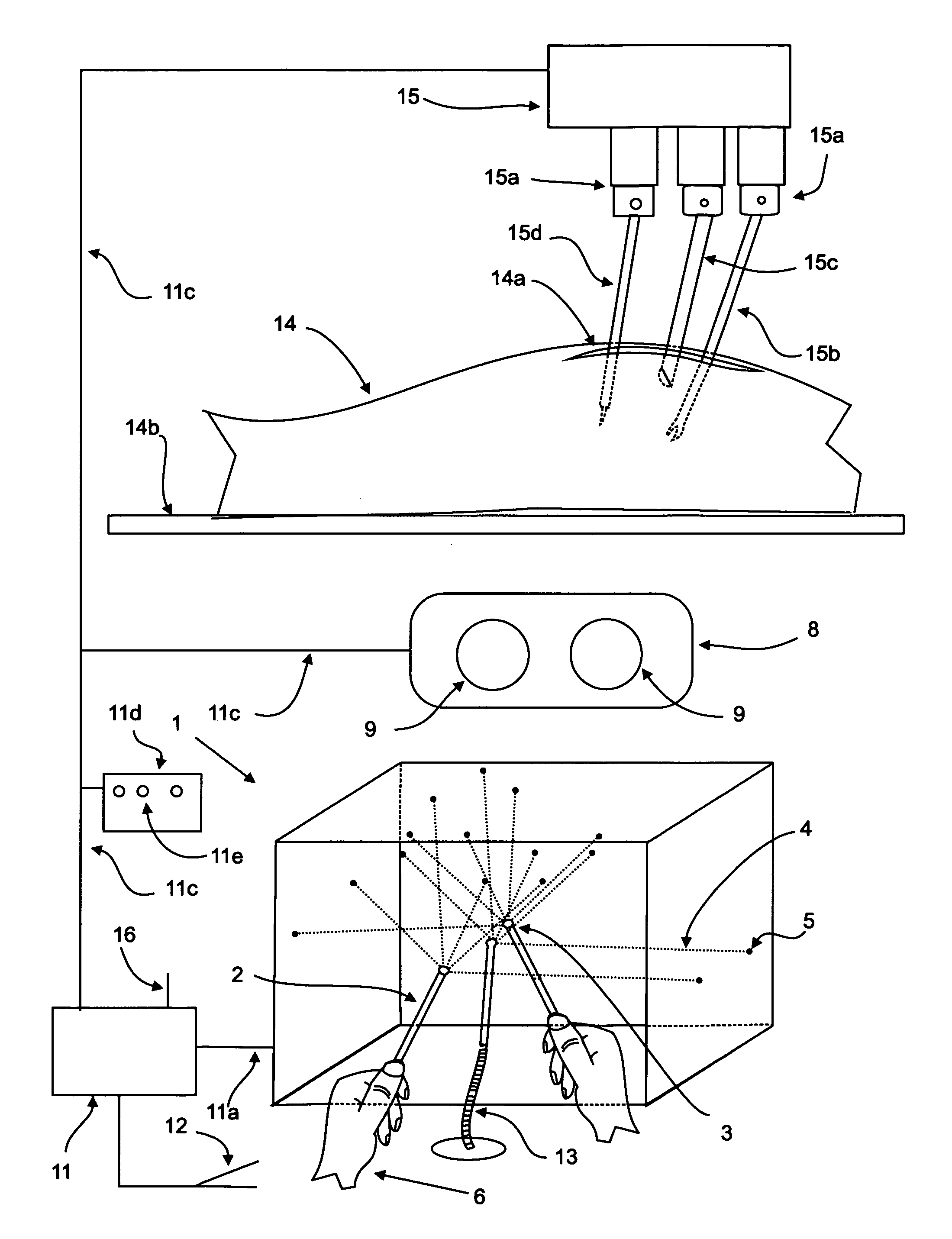
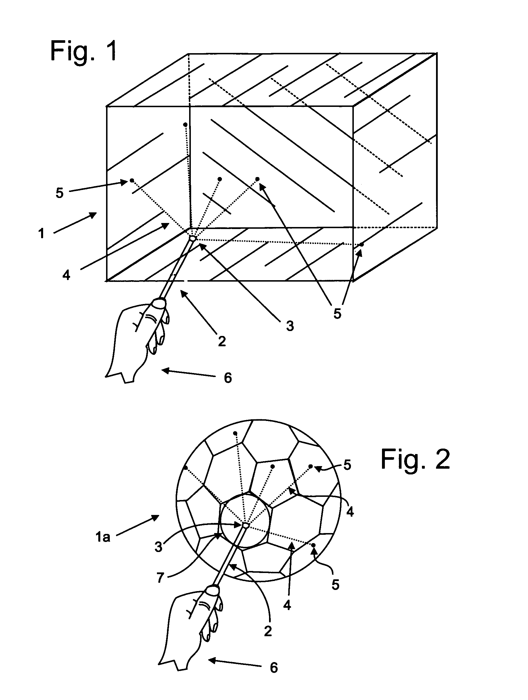
[0074]An object location, sometimes referred to as position, and orientation, sometimes referred to as attitude, will together be called the “pose” of the object, where it is understood that the orientation of a point is arbitrary and that the orientation of a line or a plane or other special geometrical objects may be specified with only two, rather than the usual three, orientation parameters.

[0075]A pose can have many spatial parameters, referred to herein as parameters. As described above, such parameters may include the location and orientation of the object. Parameters may include location information in one, two or three dimensions. Pose location parameters may also be described in terms of vectors, providing a direction and a distance. Pose orientation parameters may be defined in terms of an axis of the object, for example, the skew (rotation about the axis), rotation (rotation of the axis about an intersection of the axis and a line normal to a plane), and tilt (rotation o...


PUM


Abstract

A Robotic control system has a wand, which emits multiple narrow beams of light, which fall on a light sensor array, or with a camera, a surface, defining the wand's changing position and attitude which a computer uses to direct relative motion of robotic tools or remote processes, such as those that are controlled by a mouse, but in three dimensions and motion compensation means and means for reducing latency.

Description

CROSS-REFERENCE TO RELATED APPLICATIONS[0001]This application claims the benefit of the filing dates of U.S. Patent Application No. 60 / 904,187 filed 1 Mar. 2007 under the title LIGHT SENSOR ARRAY FORMING CAGE AROUND OPERATOR MANIPULATED WAND USED FOR CONTROL OF ROBOT OR REMOTE PROCESSES; U.S. Patent Application No. 60 / 921,467 filed 3 Apr. 2007 under the title OPERATOR MANIPULATED WAND WHICH CASTS BEAM ONTO LIGHT SENSOR ARRAY FOR CONTROL OF ROBOT OR REMOTE PROCESSES, WITH HAPTIC FEEDBACK; U.S. Patent Application No. 60 / 907,723 filed 13 Apr. 2007 under the title OPERATOR MANIPULATED WAND WHICH CASTS BEAM ONTO LIGHT SENSOR ARRAY OR SURFACE FOR CONTROL OF ROBOT OR REMOTE PROCESSES, WITH OR WITHOUT HAPTIC FEEDBACK; U.S. Patent Application No. 60 / 933,948 filed 11 Jun. 2007 under the title OPERATOR MANIPULATED WAND WHICH CASTS BEAM(S) ONTO LIGHT SENSOR ARRAY OR SURFACE FOR CONTROL OF ROBOT OR REMOTE PROCESSES IN THREE DIMENSIONS, WITH HAPTIC FEEDBACK AND MOTION COMPENSATION; U.S. Patent Ap...

Claims


Application Information

Patent Timeline
Patent Type & Authority Patents(United States)
IPC IPC(8): G06K9/00
CPCA61B19/50A61B2019/2269A61B2019/5268A61B2019/2223G06F3/0325G01D5/262A61B2019/5251A61B19/56A61B2017/00703A61B19/2203A61B2019/5255A61B2019/507G06F3/0308A61B19/22A61B2017/00207G06F3/016A61B19/5244A61B19/52A61B2019/5291A61B19/5212A61B2019/2292A61B90/36A61B2034/2055A61B2034/2068A61B34/20A61B34/70A61B34/25A61B90/361A61B34/37A61B34/74A61B34/76A61B34/10A61B2034/107A61B2034/2051A61B2090/365A61B34/30G06T11/00A61B90/06A61B2090/062H05K999/99
Inventor UNSWORTH, JOHN
Owner TITAN MEDICAL INC
Why Eureka
Try Eureka