Check patentability & draft patents in minutes with Patsnap Eureka AI!

Filling device

a filling device and filling technology, applied in the field of filling devices, can solve the problems of only changing the fill height, excessive filling product sucking back into the ring bowl, and general mechanical complexity of known systems, and achieve the effect of simple manner

Active Publication Date: 2014-08-05
KRONES AG
View PDF24 Cites 8 Cited by
  • Summary
  • Abstract
  • Description
  • Claims
  • Application Information

AI Technical Summary

Benefits of technology

[0008]It is therefore one aspect of the present disclosure to provide a device which permits to adjust the fill height in a simple manner.

Problems solved by technology

As soon as the product to be filled rises above the lower opening of the return gas tube and thereby closes the vacuum path, the filling process is stopped, the bottle is withdrawn from the filling valve, and air flowing from outside into the bottle results in the excessive filled product being sucked back into the ring bowl.
However, it is a disadvantage of these known systems that the fill height can only be changed by adjusting the height of the ring bowl or by exchanging spacers, which is complicated.
However, the known systems are generally mechanically very complex.

Method used


Image

  • Filling device
  • Filling device
  • Filling device

Examples


Embodiment Construction

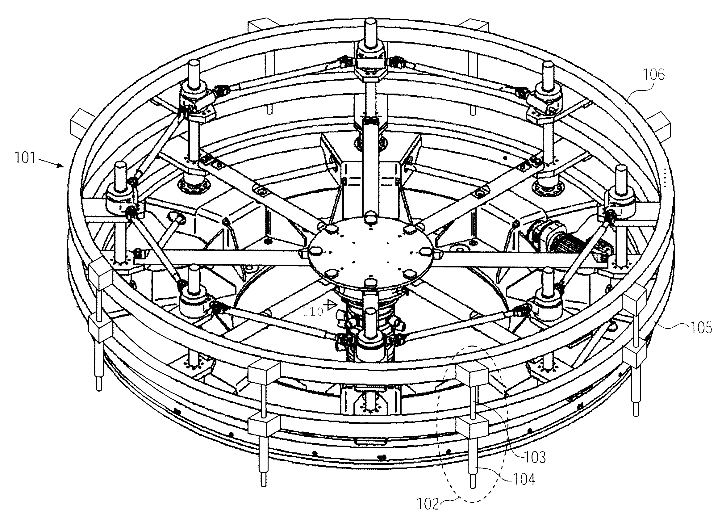
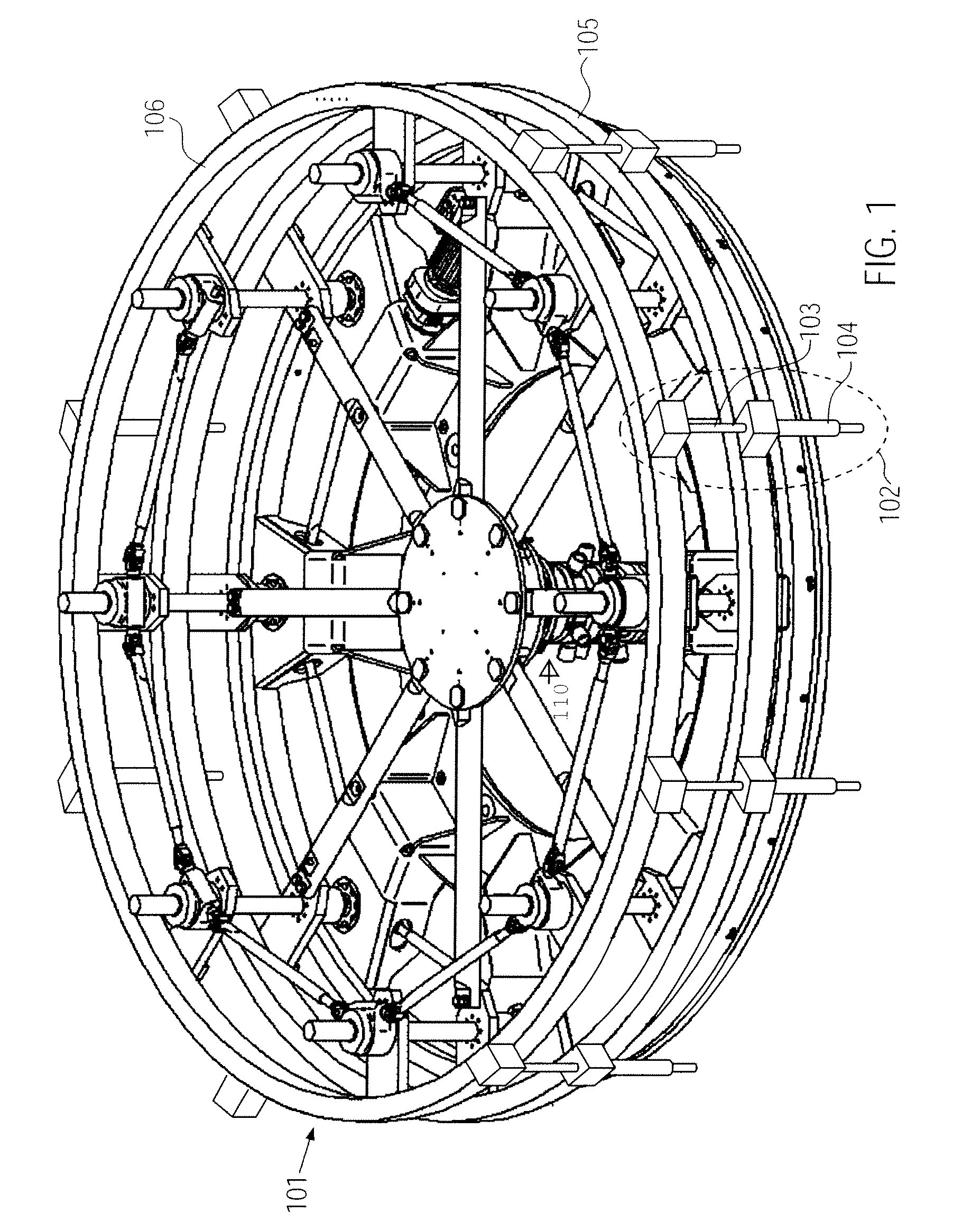
[0066]FIG. 1 shows a filler top 101 of an exemplary filling device for filling containers, for example bottles, with a liquid, for example a beverage. The filler top 101 can be mounted, for example, on a rotating filling table. In particular, the filling device can be embodied as a rotary machine.

[0067]In FIG. 1, several filling elements 102 arranged at the periphery of the filler top 101 are moreover indicated schematically. Each of the filling elements 102 comprises a return gas tube 103 and a filling tube 104, where the filling tubes 104 of the filling elements 102 are arranged at a first common support 105, and the return gas tubes 103 of the filling elements 102 are arranged at a second common support 106.

[0068]By a position adjustment means which will be described more in detail below, the position of the second common support 106 can be adjusted with respect to the position of the first common support 105. In particular, the adjustable position can correspond to a position al...


PUM


Abstract

A filling device for filling containers with a liquid, including several filling elements, each of the filling elements having a filling valve, a filling tube and a return gas tube, where the filling tubes of the filling elements are arranged at a first common support and the return gas tubes of the filling elements are arranged at a second common support, and where the position of the second common support can be adjusted relative to the position of the first common support.

Description

CROSS-REFERENCE TO RELATED APPLICATION[0001]The present application claims the benefit of priority of German Patent Application No. 102010028953.1 filed May 12, 2010. The entire text of the priority application is incorporated herein by reference in its entirety.FIELD OF THE DISCLOSURE[0002]The present disclosure relates to a filling device for filling containers with a liquid.BACKGROUND[0003]Filling devices are used, for example, in the beverage industry for filling bottles with beverages. In the process, the bottles are usually introduced into a filler with several filling elements, where each of the filling elements comprises a filling valve, a filling tube and a return vas tube. A bottle to be filled is lifted in the filler by a lifting cylinder and pressed to the filling valve outlet of a filling element by a centering bell, whereby the filling valve is opened and the product to be filled is directed from a ring bowl into the bottle.[0004]Usually, vacuum is applied to the ring ...

Claims


Application Information

Patent Timeline
Patent Type & Authority Patents(United States)
IPC IPC(8): B65B31/00B67C3/22B67C3/26
CPCB67C3/22B67C2003/2668
Inventor GRUBER, WOLFGANGNEUMAYER, WALTERKNIELING, ERWIN
Owner KRONES AG
Features
  • R&D
  • Intellectual Property
  • Life Sciences
  • Materials
  • Tech Scout
  • Unparalleled Data Quality
  • Higher Quality Content
  • 60% Fewer Hallucinations
Learn More