

Quick adjustable clamp
a clamp and adjustable technology, applied in the field of clamps, can solve the problems of inconvenient use of conventional clamps, labor-intensive and time-consuming adjustment of spans,
- Summary
- Abstract
- Description
- Claims
- Application Information
AI Technical Summary
Benefits of technology
Problems solved by technology
Method used
Image

Examples
Embodiment Construction
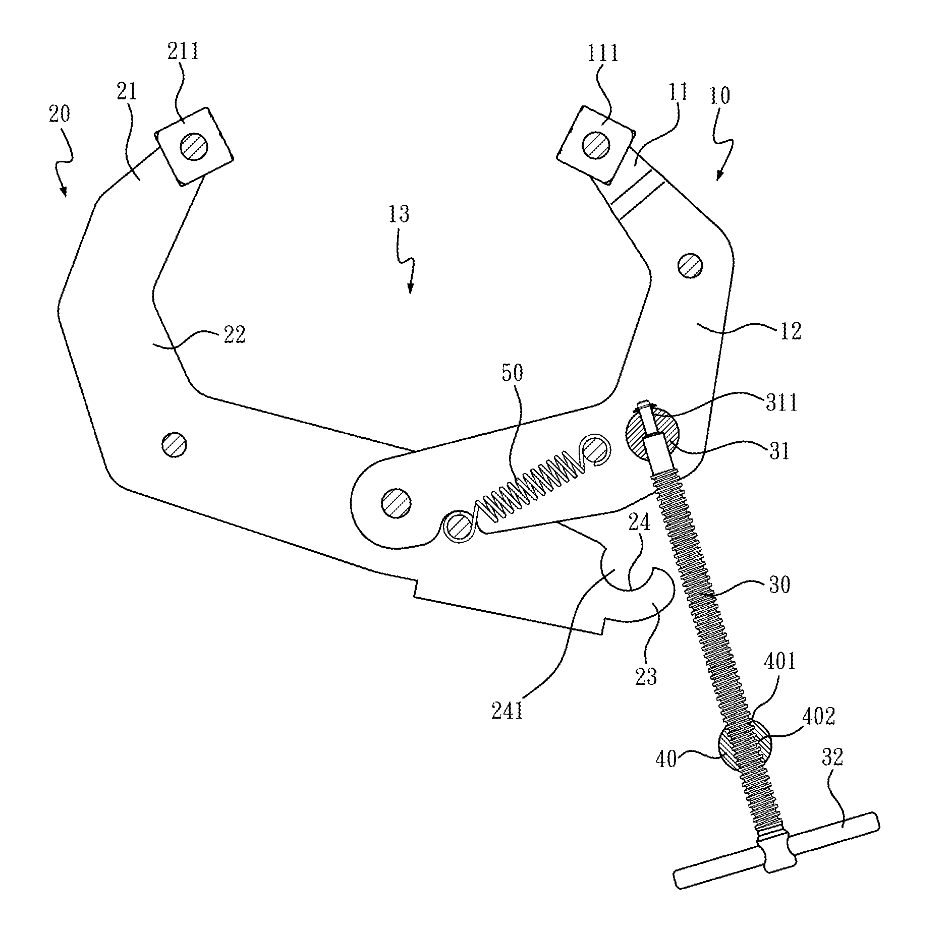
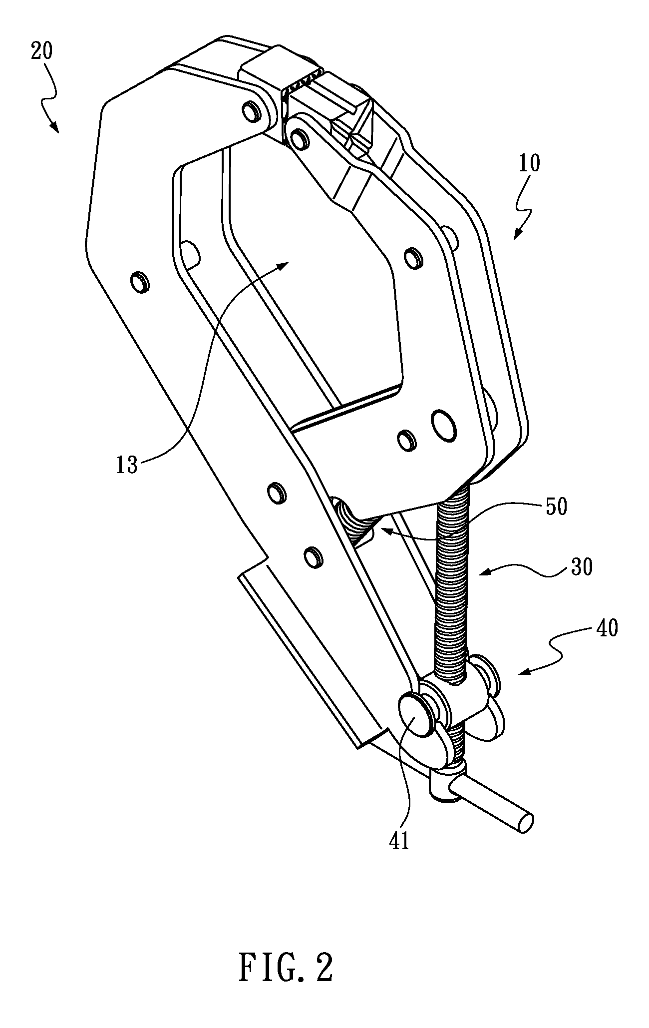
[0025]Referring to FIG. 2 through FIG. 4, the present invention provides a quick adjustable clamp primarily comprising a first clamp jaw 10, a second clamp jaw 20, a driving screw 30, a nut 40 and a spring 50.
[0026]The first clamp jaw 10 has one end configured to be a first working end 11, to which a first clamping chunk 111 is rotatably attached.
[0027]The second clamp jaw 20 has one end configured to be a second working end 21, to which a second clamping chunk 211 is rotatably attached. The second clamp jaw 20 and the first clamp jaw 10 are pivotally connected at their ends opposite to the first and second working ends 11, 21, such that the first working end 11 and the second working end 21 are allowed to be drawn together or away from each other. In addition, the first clamp jaw 10 includes a first bent section 12 near the first working end 11 while the second clamp jaw 20 includes a second bent section 22 near the second working end 21, such that the first working end 11 and the ...
PUM
 Abstract
Description
Claims
Application Information