Supercharge Your Innovation With Domain-Expert AI Agents!

Methods and systems for treating a bifurcation with provisional side branch stenting

a provisional side branch and stenting technology, applied in the field of medical devices, can solve the problems of limited success rate, stents and connecting balloon catheter portions may obstruct the use of post-operative devices to treat a daughter vessel, and stents are not fully able to prevent in-stent restnosis (isr) or caused restnosis

Active Publication Date: 2014-08-05
ADVANCED BIFURCATION SYST
View PDF583 Cites 25 Cited by
  • Summary
  • Abstract
  • Description
  • Claims
  • Application Information

AI Technical Summary

Benefits of technology

[0016]One of the first elongate shaft or the second elongate shaft may comprise a region having a guidewire lumen, an inflation lumen, and an exchange lumen. The other elongate shaft may be slidably disposed in the exchange lumen. The expandable member on the other elongate shaft may be axially spaced apart from the first elongate shaft having the exchange lumen such that the expandable member on the other shaft is distal to the expandable member on the elongate shaft with the exchange lumen. The system may comprise a capture tube having a proximal end, a distal end, a longitudinal axis, and a central channel extending therebetween. The first elongate shaft and the second elongate shaft may be slidably disposed in the central channel. The capture tube may prevent the first elongate shaft from tangling with the second elongate shaft. The capture tube may comprise a perforated region extending along the longitudinal axis, extending at least partially between the proximal and distal ends of the capture tube so that the capture tube may be peeled away from the first and second elongate shafts. The capture tube may also comprise a locking mechanism for releasably holding the first elongate shaft and the second elongate shaft.
[0017]One of the first elongate shaft or the second elongate shaft may comprise a snap fitting configured to receive and retain the other elongate shaft. The other elongate shaft may be slidably movable axially through the snap fitting, and the expandable member on the other elongate shaft may be axially spaced apart from the elongate shaft having the snap fitting such that the expandable member on the other elongate shaft is distal to the expandable member on the elongate shaft with the snap fitting. The system may comprise a polymer sleeve having a proximal end, a distal end, a longitudinal axis, and a central channel extending therebetween. The first elongate shaft and the second elongate shaft may be slidably disposed in the central channel. The polymer sleeve may prevent the first elongate shaft from tangling with the second elongate shaft.

Problems solved by technology

Conventional stents have been used for treating more complex vascular problems, such as lesions at or near bifurcation points in the vascular system, where a secondary artery branches out of a typically larger, main artery, with limited success rates.
Furthermore, the configuration of struts and connecting balloon catheter portions may obstruct the use of post-operative devices to treat a daughter vessel in the region of a vessel bifurcation.
Regular stent design has typically compromised one consideration for the other in an attempt to address both.
Although conventional stents are routinely used in clinical procedures, clinical data shows that these stents are not capable of completely preventing in-stent restenosis (ISR) or restenosis caused by intimal hyperplasia.
Patients treated with coronary stents can suffer from in-stent restenosis.
However, success with the systemic approach has been limited.
Systemic delivery of drugs is inherently limited since it is difficult to achieve constant drug delivery to the afflicted region and since systemically administered drugs often cycle through concentration peaks and valleys, resulting in time periods of toxicity and ineffectiveness.
Furthermore, where a definition or use of a term in a reference, which is incorporated by reference herein is inconsistent or contrary to the definition of that term provided herein, the definition of that term provided herein applies and the definition of that term in the reference does not apply.

Method used


Image

  • Methods and systems for treating a bifurcation with provisional side branch stenting
  • Methods and systems for treating a bifurcation with provisional side branch stenting
  • Methods and systems for treating a bifurcation with provisional side branch stenting

Examples


Embodiment Construction

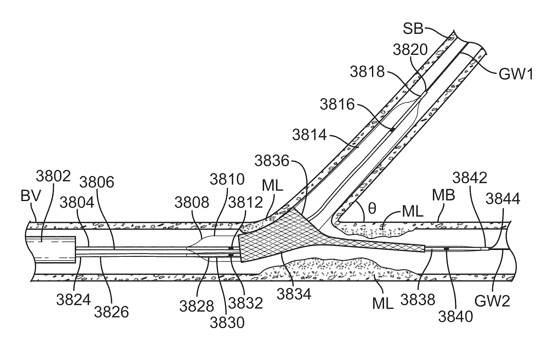
[0064]The present invention relates to delivery systems for delivery of stents to vessel bifurcations having a main branch and a side branch, and is generally configured to at least partially cover a portion of a the side branch as well as a portion of the main branch. However, this is not intended to be limiting, and one of skill in the art will appreciate that the devices and methods described herein may be used for treating other regions of the body.

[0065]The scientific community is slowly moving away from a main branch vs. side branch model and nomenclature. It is now well accepted that a “mother” vessel bifurcates into two “daughter vessels,” the two vessels that are anatomically after the carina. The vessel that appears to be the continuation of the mother vessel is usually less angulated. The other vessel may is frequently smaller in diameter and may be commonly referred to as the side branch, or a daughter vessel. Therefore, in this specification, the terms “main branch,”“tr...


PUM


Abstract

A system for treating a bifurcation includes first and second delivery catheters, each having an expandable member. A stent having a side hole is disposed on the second delivery catheter. A portion of the first delivery catheter is disposed under a portion of the stent. The first delivery catheter is slidable relative to the second delivery catheter, and the first delivery catheter passes through the side hole. Expansion of the first expandable member expands a portion of the stent and expansion of the second expandable member expands the rest of the stent.

Description

CROSS-REFERENCES TO RELATED APPLICATIONS[0001]The present application is a continuation in part of International PCT Application No. PCT / US2009 / 058505 filed Sep. 25, 2009 which claims the benefit of U.S. Provisional Patent Application No. 61 / 194,346 filed Sep. 25, 2008, the entire contents of each of which are incorporated herein by reference. The present application is also a non-provisional of, and claims the benefit of U.S. Provisional Patent Application No. 61 / 317,114, filed Mar. 24, 2010, the entire contents of which are incorporated herein by reference.[0002]The present application is related to U.S. patent application Ser. No. 13 / 071,149, filed the same day as the present application. The present application is also related to U.S. patent application Ser. Nos. 13 / 071,251; 13 / 071,239; 13 / 071,183; and 13 / 071,162; each filed on the same day as the present application, and each of which is incorporated herein by reference. The present application is also related to U.S. Provision...

Claims


Application Information

Patent Timeline
Patent Type & Authority Patents(United States)
IPC IPC(8): A61F2/954A61F2/06A61M25/10A61F2/958
CPCA61F2/954A61F2/958A61M2025/1079A61M2025/1045A61M25/1002A61F2/915A61F2/91A61F2230/001A61F2/86A61F2/856
Inventor BOURANG, HENRYKHORSANDI, MEHRAN
Owner ADVANCED BIFURCATION SYST
Features
  • R&D
  • Intellectual Property
  • Life Sciences
  • Materials
  • Tech Scout
  • Unparalleled Data Quality
  • Higher Quality Content
  • 60% Fewer Hallucinations
Learn More