Axial magnetic suspension

a technology of axial magnetic suspension and magnetic plate, which is applied in the direction of magnets, magnetic bodies, mechanical equipment, etc., can solve the problems of increasing the face surface area of magnets, and the need to increase the depth or thickness

Inactive Publication Date: 2014-08-12
ARONSTAM PETER S +1
View PDF20 Cites 12 Cited by
  • Summary
  • Abstract
  • Description
  • Claims
  • Application Information

AI Technical Summary

Problems solved by technology

Due to structural and form factor machine constraints, it is often not possible to increase the face surface area of the magnets, but rather the depth or thickness must be increased.

Method used


Image

  • Axial magnetic suspension
  • Axial magnetic suspension
  • Axial magnetic suspension

Examples


Embodiment Construction

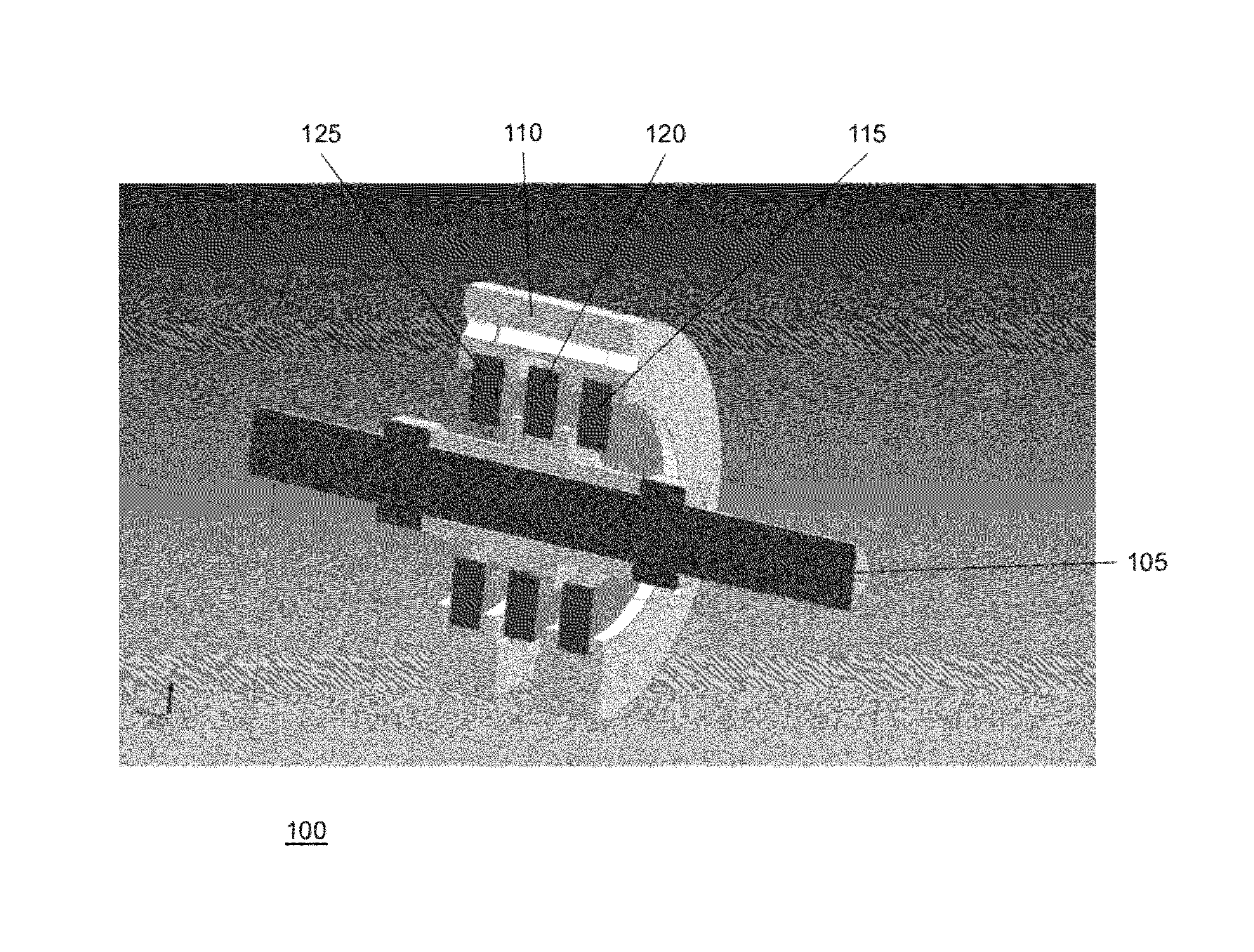
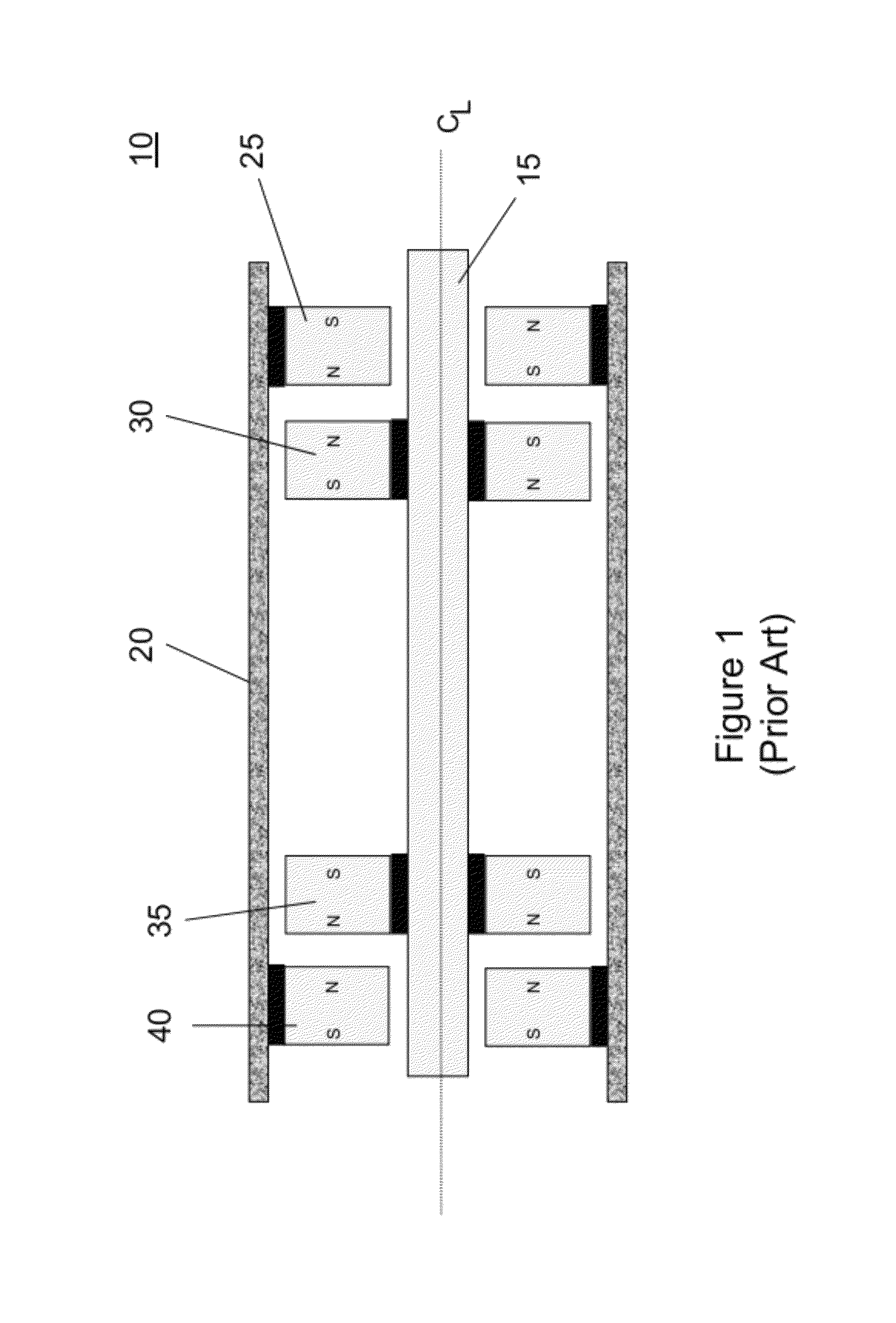
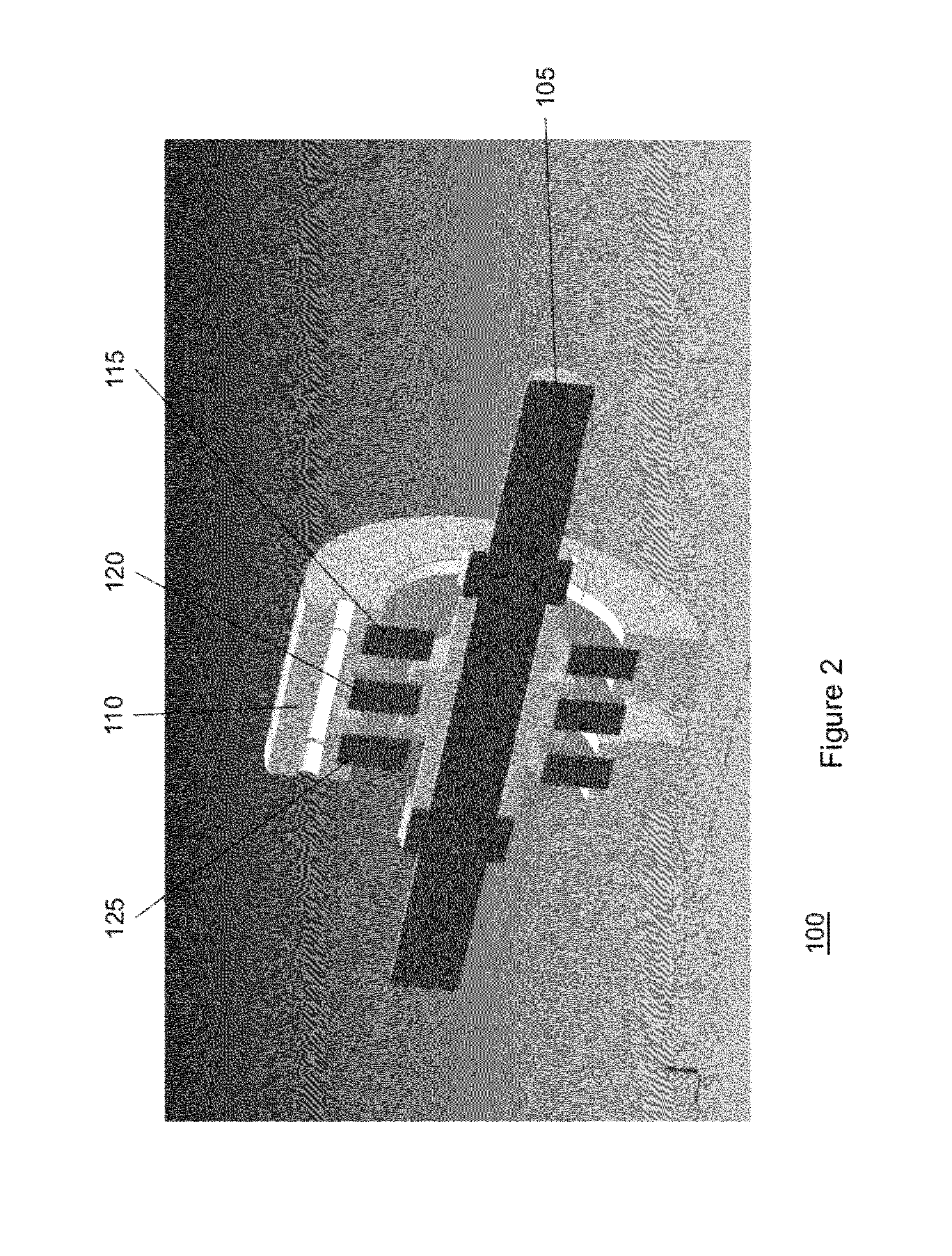
[0023]The present invention is generally directed to a suspension assembly which can be selected based upon desired design parameters. The suspension assembly will be described herein in relation to rotating machinery, such as turbines. It is to be understood, however, that the suspension assembly may also be used for other types of machinery without departing from principles of the present invention and that shaft or housing rotation is not required. Vertical support of variable load masses is also to be considered part of the present invention. Additionally, the suspension system will be described in relation to members that are made from magnetic materials. It is to be understood, however, that the members may be made from other materials that are configured to generate forces on adjacent members. To better understand the novelty of the suspension assembly of the present invention and the methods of use thereof, reference is hereafter made to the accompanying drawings. The presen...


PUM


Abstract

The present invention generally relates to an apparatus and method for axially supporting a shaft. In one aspect, a magnetic suspension system for supporting a shaft in a housing is provided. The magnetic suspension system includes an array of magnet members disposed between the shaft and the housing. The array of magnet members comprising a first magnet member, a second magnet member, and a third magnet member, wherein the first magnet member and the second magnet member generate a first force that is substantially parallel to a longitudinal axis of the shaft and the second magnet member and the third magnet member generate a second force that is substantially parallel with the longitudinal axis of the shaft The first force and the second force are configured to position the shaft axially within the housing. In another aspect, a method of supporting a shaft along a longitudinal axis of a housing is provided. In a further aspect, a suspension system for supporting a shaft in a housing is provided.

Description

CROSS-REFERENCE TO RELATED APPLICATIONS[0001]This application claims benefit of U.S. provisional patent application Ser. No. 61 / 356,572, filed Jun. 19, 2010, which is herein incorporated by reference.BACKGROUND OF THE INVENTION[0002]1. Field of the Invention[0003]Embodiments of the present invention generally relate to the support of machinery. More particularly, the invention relates to an apparatus and method for axially supporting a shaft or other mass that is laterally supported.[0004]2. Description of the Related Art[0005]A conventional magnetic suspension assembly is based on the repulsive force which exists between two similar magnetic poles. An example of a conventional magnetic suspension assembly is illustrated in FIG. 1. As shown, the conventional magnetic suspension assembly 10 includes a shaft 15 disposed within a housing 20. As illustrated, a first pair of opposing magnets 25, 30 is positioned on one end of the rotating shaft 15 and a second pair of opposing magnets 35...

Claims


Application Information

Patent Timeline
Patent Type & Authority Patents(United States)
IPC IPC(8): H02K7/09
CPCF16C39/063F16C2360/23F16C2240/12F16C32/0427H01F7/0236F16C2360/00
Inventor ARONSTAM, PETER S.FINCHER, ROGER W.
Owner ARONSTAM PETER S
Why Eureka
Try Eureka