Operating control having specific feedback

a technology of operating control and specific feedback, which is applied in the direction of pulse technique, instrumentation, and signal processing systems, etc., can solve the problems of difficult for an operator to recognize if the operating control is operating, complicated structure of the device outputting the desired feedback signal, and only suitable piezoelements

Active Publication Date: 2014-08-12
LISA DRAXLMAIER GMBH
View PDF19 Cites 31 Cited by
  • Summary
  • Abstract
  • Description
  • Claims
  • Application Information

AI Technical Summary

Benefits of technology

[0014]Advantageously, the oscillator coil is connected with the actuating element and a fixing element (mounting element). In this preferred embodiment, the oscillator coil is, thus, a connecting element between the actuating element and the mounting element. In this way, a relative motion between the actuating element and the mounting element may easily be recognized by means of the oscillator coil.
[0024]It is particularly preferred that the memory element is configured for storing arbitrary, preferably periodic, approximated signals, most preferably signals approximated by a Fourier series. In this way, even a complicated compound signal may quickly be retrieved and does not have to be recalculated by the controller element first. In this case, the calculation means the selection of the frequencies to be superimposed together with their respective amplitudes.
[0035]According to the invention, the described operating control is used for applying the method of the invention. The use of an oscillator coil for emitting the mechanical feedback signal makes it possible to apply almost arbitrary signal shapes and large signal amplitudes or large signal forces in a wide frequency range to the actuating element. Thus, a simple structure is provided, which is suitable for emitting haptic and / or acoustic feedback signals, wherein the feedback signals are very well adaptable and, thus, specifically adjustable to the event to be indicated. The operating control according to the invention is thus eminently suitable for use in a motor vehicle in which a driver, whose eyes are directed to the events outside of the vehicle, may control different electronic components in the vehicle, such as communication systems like a car phone, driver assistance systems like a navigation system or an on-board computer, multimedia appliances such as a car stereo, comfort systems such as ventilation and air conditioning, or even vehicle operation systems such as gear shift, cruise control, windshield wipers or the like.

Problems solved by technology

In particular in operating controls having actuating elements that are not mechanically moved upon actuation, it is often difficult for an operator to recognize if the operating control has realized and implemented the desired actuation.
However, the device disclosed in that document has the disadvantage, that two separate elements, that is the sound generator and the haptic converter, need to be used.
This results in a complicated structure of a device outputting the desired feedback signal.
Thus, the piezoelement is only suitable for a haptically perceivable output of discrete resonance frequencies of the overall system to which the piezoelectric element is connected.
This limits the type and the frequency bandwidth of the feedback that can be output by this method.

Method used


Image

  • Operating control having specific feedback
  • Operating control having specific feedback
  • Operating control having specific feedback

Examples


first embodiment

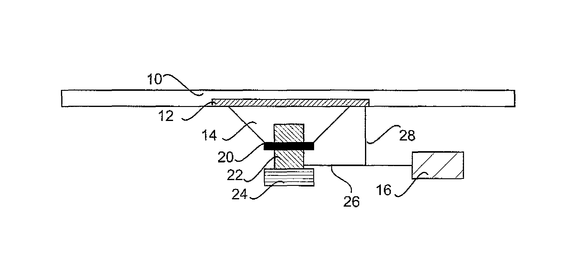
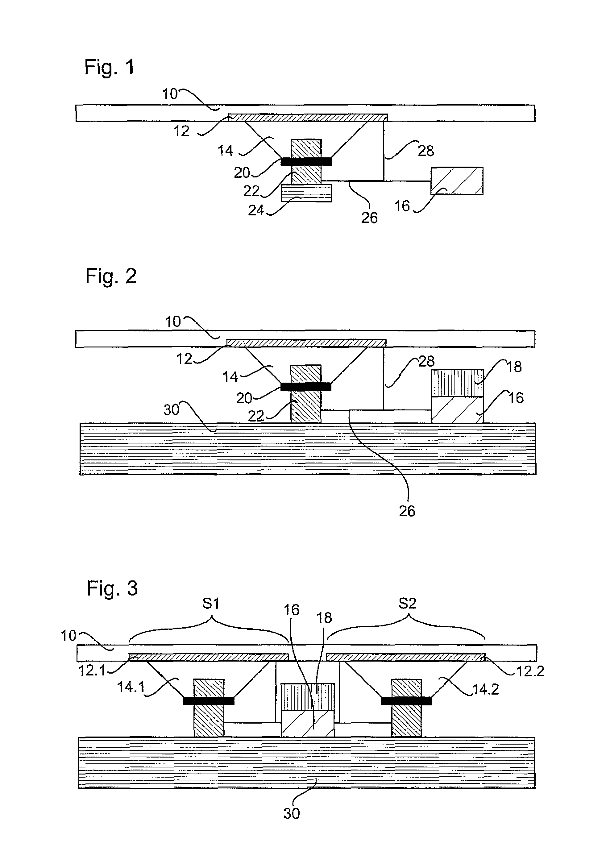
[0041]FIG. 1 shows a first preferred embodiment of an operating control. An actuating element 10 is provided with a sensor element 12 which is capable of registering contact (touch) with the actuating element 10. The actuating element 10 is configured as a contact element having a surface and may, for example, be a decorative part or a form part made of metal, wood or plastic or the like. The actuating element 10 is actuated by a user touching the surface of the actuating element 10, for example. Accordingly, the sensor element 12 is a pressure or proximity sensor, wherein this sensor may be formed by a piezo sensor, a force sensing resistor (FSR) or a capacitive sensor. The actuating element 10 which otherwise only provides a decorative function, thus constitutes at the same time a protective layer for the sensor element 12 against undue outer influences (impact) onto the sensor element 12. In the operating control shown in FIG. 1, the actuating element 10 is formed by a wooden orn...

second embodiment

[0045]FIG. 2 shows an operating control which differs from the operating control of the embodiment shown in FIG. 1 in that in place of the mass element 24 shown in FIG. 1 a mounting element 30 is provided in the embodiment shown in FIG. 2. The mounting element 30 is fixed at least with respect to the actuating element 10 so that a force between the mounting element 30 and the actuating element 10 is applied through the oscillator coil 14, in particular the coil member 20 and the magnet member 22. In particular, also at low frequencies of the feedback signal, the force applied by the oscillator coil 14 onto the actuating element 10 causes a larger deformation of the actuating element 10 than possible in the case of the embodiment having the mass element 24 and shown in FIG. 1. Moreover, due to the circumstance that the oscillator coil 14 may rest against the mounting element 30, higher forces may be transmitted onto the actuating element 10, too.

[0046]Further, in the embodiment of th...


PUM


Abstract

An operating control, in particular in a motor vehicle, wherein the operating control has at least one actuating element for actuating the operating control. The operating control comprises at least one sensor element operatively connected to the actuating element for registering an actuation, and at least one oscillator coil fixedly connected to the actuating element for emitting a mechanical feedback signal, in particular bending waves, through the actuating element. The feedback signal is haptically and / or acoustically perceivable, preferably simultaneously haptically and acoustically perceivable. The operating control includes a controller element for activating the oscillator coil in case of actuation of the operating control.

Description

TECHNICAL FIELD[0001]The invention concerns an operating control, in particular in a motor vehicle, which comprises at least an actuating element for actuating the operating control and at least a sensor element operatively connected with the actuating element for registering an actuation. Further, the invention concerns a component of a vehicle interior having such an operating control as well as a method for outputting feedback of an operating control.PRIOR ART[0002]In particular in operating controls having actuating elements that are not mechanically moved upon actuation, it is often difficult for an operator to recognize if the operating control has realized and implemented the desired actuation. In operating controls such as press switches or push buttons, the operator can easily understand if the switch or push button has been operated correctly. This happens for example by locking in of a switch or by exceeding a mechanical pressure point so that the operator is immediately ...

Claims


Application Information

Patent Timeline
Patent Type & Authority Patents(United States)
IPC IPC(8): G08B6/00
CPCH03K17/96B60K2350/1036G06F3/016G06F3/03547H03K2217/96062B60K2370/1446B60K2370/158
Inventor STECKEL, MICHAELRUTER, KARSTENKREIS, RAIMUND
Owner LISA DRAXLMAIER GMBH
Why Eureka
Try Eureka