
Method of calculating lens shading compensation factor and method and apparatus for compensating for lens shading by using the method

a compensation factor and lens shading technology, applied in the field of compensating for lens shading, can solve the problems of large amount of memory and large amount of memory, and achieve the effect of improving the compensation performan

Active Publication Date: 2014-08-12
LG INNOTEK CO LTD
View PDF12 Cites 9 Cited by
  • Summary
  • Abstract
  • Description
  • Claims
  • Application Information

AI Technical Summary

Benefits of technology

This patent describes a way to compensate for shading in cameras by using a small amount of memory. This method improves the quality of the compensation.

Problems solved by technology

Other methods also require a large amount of memory.
Devices requiring a large amount of memory may cause various issues.

Method used


Image

  • Method of calculating lens shading compensation factor and method and apparatus for compensating for lens shading by using the method
  • Method of calculating lens shading compensation factor and method and apparatus for compensating for lens shading by using the method
  • Method of calculating lens shading compensation factor and method and apparatus for compensating for lens shading by using the method

Examples


first embodiment

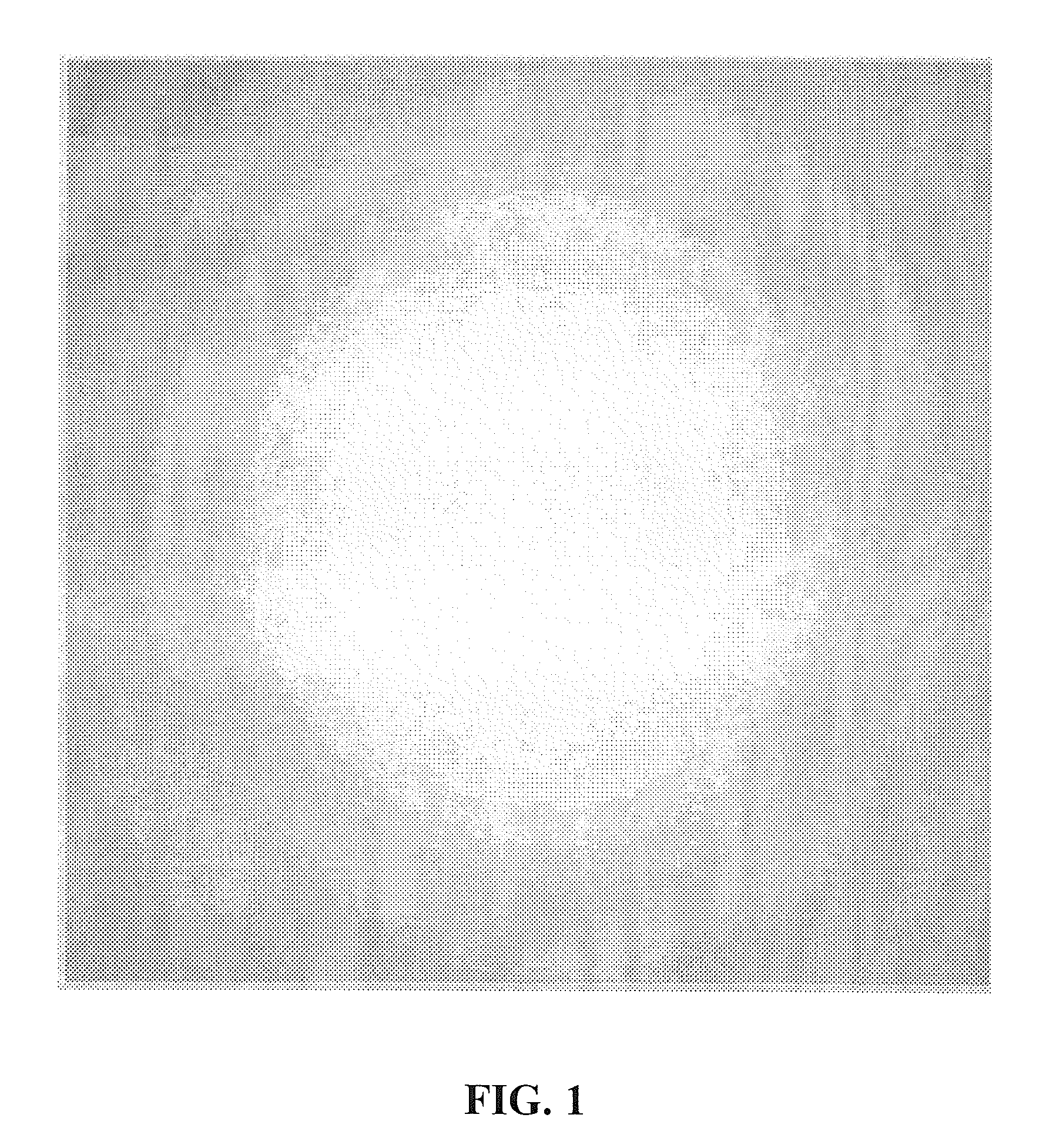
[0040]According to a first embodiment, a method of compensating for the characteristic of the lens shading that an image decreases in brightness from the center thereof to the periphery thereof will now be described.

[0041]A reference image such as the image as illustrated in FIG. 1, which decreases in brightness from the center thereof to the periphery thereof, may be divided into N sectors that have circular belt shapes with the same center and different radii, as illustrated in FIG. 3. Each sector may be a group of pixels having similar pixel values. For example, when pixel values range from 0 to 255, differences between pixel values of pixels constituting each sector may be 5 or less.

[0042]Then, the maximum one of the pixel values of the reference image, and a mean pixel value of each sector are determined. At this point, the pixel having the maximum value is located in the center of the reference image.

[0043]A compensation factor F1 of each sector having a circular belt shape ma...

second embodiment

[0059]The first embodiment is adapted to the case that a reference image decreases in brightness from the center thereof to the periphery thereof, but is not adapted to the case that pixel values are irregularly distributed. A second embodiment is adapted even to the case that a reference image is asymmetric, and pixel values are irregularly distributed. The second embodiment is different from the first embodiment after a reference image is divided into images according to color channels.

[0060]The reference image is assumed to have a distribution as illustrated in FIG. 8. Like in the FIG. 4, the reference image is placed on the x-y plane, and the z-value denotes a brightness value of each pixel. Referring to FIG. 8, the center of the reference image is not brighter than the others, and the reference image does not gradually decrease in brightness from the center thereof to the periphery thereof and has no specific pattern.

[0061]To perform a lens shading compensation process on the i...


PUM


Abstract

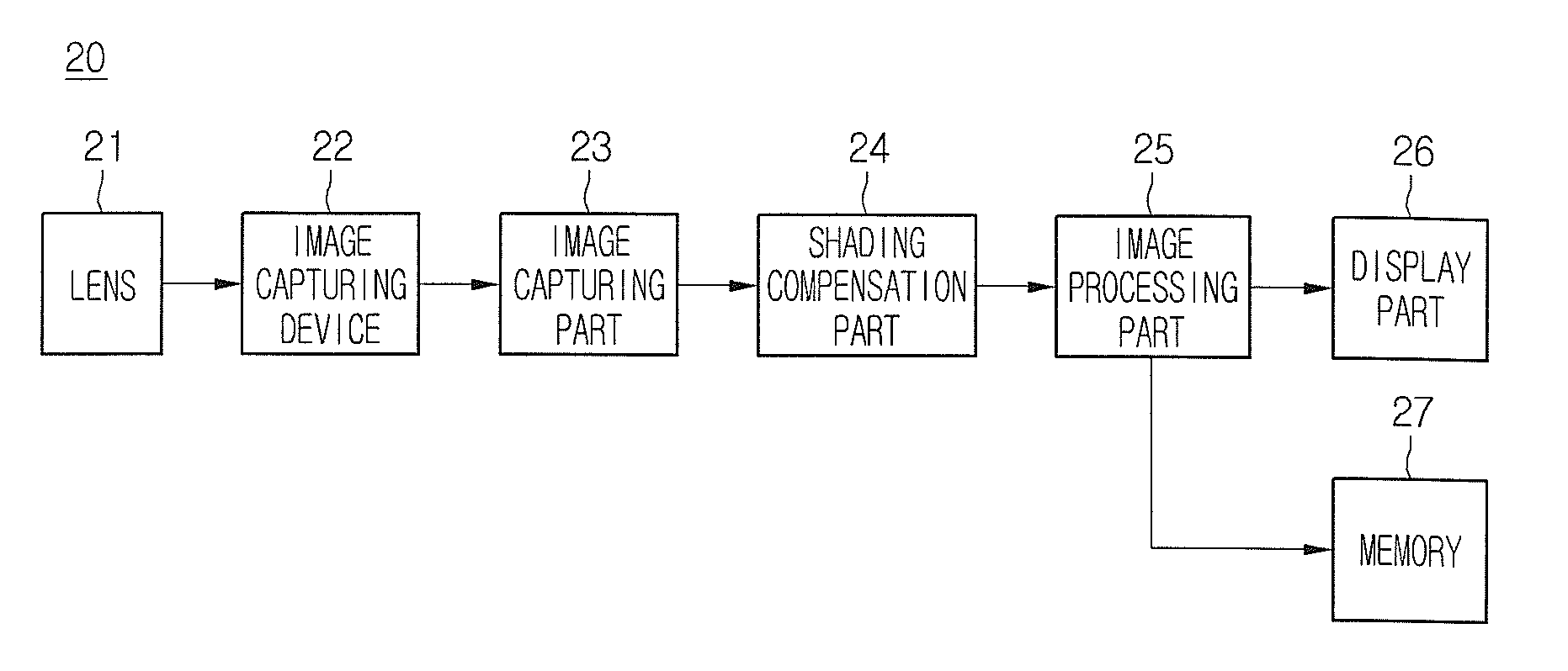
Provided is a method of calculating a compensation factor to compensate for lens shading due to the characteristics of an image capturing device, which requires a small amount of memory. A reference image is captured, and a compensation factor is calculated using the characteristics of a lens shading pattern of the captured reference image. A distribution of pixel values is approximated using an exponential spline function, and a compensation factor is calculated using the approximated distribution. In addition, a method and an apparatus for compensating for lens shading by using a calculated compensation factor are provided.

Description

CROSS-REFERENCE TO RELATED APPLICATION[0001]This application claims the benefit under 35 U.S.C. §119 to Korean Patent Application No. 10-2011-0063821, filed Jun. 29, 2011, which is hereby incorporated by reference in its entirety.BACKGROUND[0002]The present disclosure relates to a method of compensating for lens shading, and more particularly, to a method of calculating a compensation factor to compensate for lens shading due to the characteristics of an image capturing device, which requires a small amount of memory. According to an embodiment, a white image is captured, and a compensation factor is calculated using the characteristics of a lens shading pattern of the captured white image. According to another embodiment, a distribution of pixel values is approximated using an exponential spline function, and a compensation factor is calculated using the approximated distribution. In addition, a method and an apparatus for compensating for lens shading by using a calculated compens...

Claims


Application Information

Patent Timeline
Patent Type & Authority Patents(United States)
IPC IPC(8): H04N9/64H04N5/20H04N23/12
CPCH04N5/3572H04N25/61H04N25/136H04N1/40H04N9/64H04N9/77
Inventor PARK, SOO JINBIJALWAN, DEEPAK CHANDRAGUPTA, RAGHUBANSH B.
Owner LG INNOTEK CO LTD
Learn More