Amplifying device

Active Publication Date: 2005-10-25
KOKUSA ELECTRIC CO LTD
View PDF8 Cites 0 Cited by
  • Summary
  • Abstract
  • Description
  • Claims
  • Application Information

AI Technical Summary

Benefits of technology

[0015]The present invention has been made in view of the above, and has an object to provide an amplifying device which is reduced in size, weight and cost and which can improve the distortion compensation performance.
[0016]For solving the foregoing problem of the prior art, according to the present invention, there is provided an amplifying device, wherein input signals are, per carrier, subjected to digital orthogonal modulation and further to offset rotation processing in digital orthogonal modulating sections, then combined in a coupling section, and a digital delay section for performing digital-delaying for a constant time is used in a main signal system or a control system instead of an analog delay line, and further, a distortion compensating section gives distortion compensation to a multi-carrier signal for canceling a nonlinear characteristic generated in an amplifying section, based on a power value and a portion of an output from a distributing section. Therefore, the amplifying device according to the present invention requires no analog delay lines and enables a phase control between the main signal system and the control system in the digital orthogonal modulating sections, and thus can be provided with reduced size, weight and cost.
[0017]According to the present invention, there is also provided an amplifying device, wherein input signals are, per carrier, subjected to digital orthogonal modulation and further to offset rotation processing in digital orthogonal modulating sections, then combined in a coupling section, and a digital delay section for performing digital-delaying for a constant time is used in a main signal system or a control system instead of an analog delay line, and further, a distortion compensating section controls a multi-carrier signal for reducing an error between the demodulated contents of outputs from an up-convert section and a distributing section relative to a power value. Therefore, the amplifying device according to the present invention requires no analog delay lines and enables a phase control between the main signal system and the control system in the digital orthogonal modulating sections, and thus can be provided with reduced size, weight and cost.

Problems solved by technology

However, since an amplifier is an analog device, its input-output characteristics form a nonlinear function.
This nonlinear output causes nonlinear distortion.
On the other hand, in case of a signal after passing the amplifier, nonlinear distortion is generated so that a signal component leaks to the exterior of the desired signal band (adjacent channels).
Under these circumstances, it has been a large problem how to reduce the foregoing adjacent channel leak power.
However, since the foregoing conventional amplifying device uses the analog delay line to delay the input signal, it is increased in size, weight and cost.
However, while the phase control with higher accuracy than that of the amplifying device of FIG. 5 is required for matching the phases, it is difficult to realize it, which has been a problem for improving the distortion compensation performance.

Method used


Image

  • Amplifying device
  • Amplifying device
  • Amplifying device

Examples


Embodiment Construction

[0023]Preferred embodiments of the present invention will be described hereinbelow with reference to the accompanying drawings.

[0024]Function realizing sections which will be described hereinbelow, each may be any circuit or device, or a part of or the whole of its function may be realized by software, as long as it can realize such a function. Further, the function realizing section may be realized by a plurality of circuits, or the plurality of function realizing sections may be realized by a single circuit.

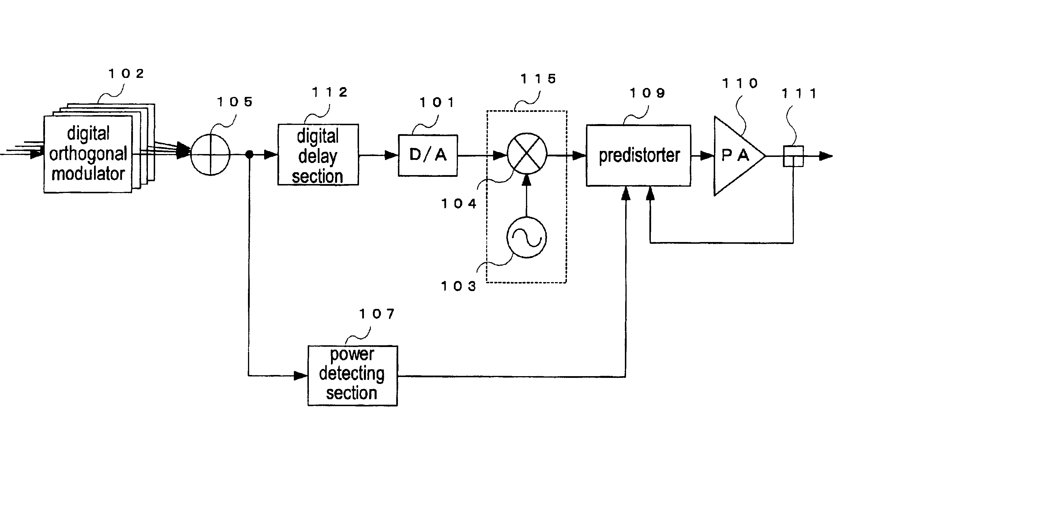
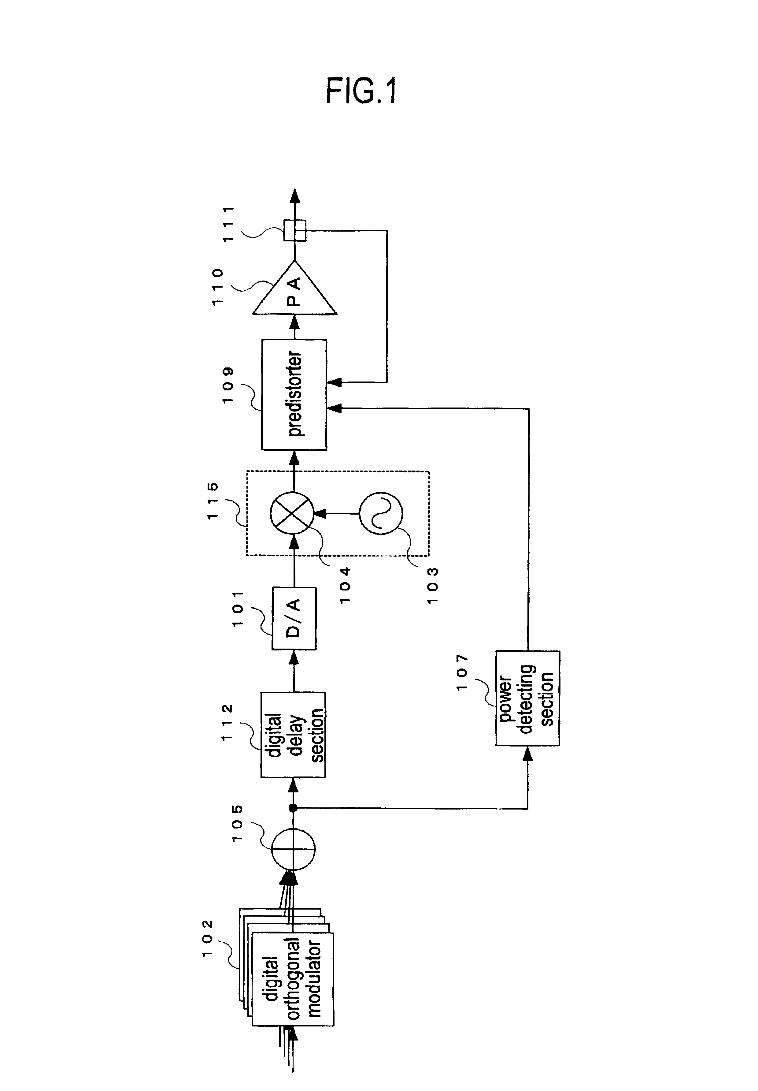
[0025]In an amplifying device according to the embodiment of the present invention, input signals are, per carrier, subjected to digital orthogonal modulation and further to offset rotation processing in digital orthogonal modulating sections, then combined in a coupling section, and a digital delay section for performing digital-delaying for a constant time is used in a main signal system or a control system instead of an analog delay line, and further, a distortion compensati...


PUM


Abstract

To provide an amplifying device which is reduced in size, weight and cost and which can improve the distortion compensation performance. In the amplifying device, input signals are each subjected to digital orthogonal modulation using an IF and further to offset rotation processing in digital orthogonal modulators, then bifurcated into a main signal system and a control system, and detection of a power value is performed at an IF band in a power detecting section of the control system. Therefore, offset rotation processing of the input signals in the power detection is not required, so that a structure for matching phases of a multi-carrier signal and a power value signal is not required, resulting in improving the distortion compensation performance without using an analog delay line.

Description

BACKGROUND OF THE INVENTION[0001]1. Field of the Invention[0002]The present invention relates to a mobile communication system, such as a portable telephone system, and in particular, to an amplifying device for use in a base station device.[0003]2. Description of the Related Art[0004]In the mobile communication system, such as the portable telephone system, a base station device is required to ensure arrival of a radio signal at a mobile station device which is located far from the base station device. Accordingly, it is necessary for the base station device to largely amplify a signal through an amplifier for transmitting it.[0005]In the foregoing mobile communication system, the W-CDMA (Wide-band Code Division Multiple Access) system and so on have been adopted as mobile communication systems.[0006]However, since an amplifier is an analog device, its input-output characteristics form a nonlinear function. Particularly, after exceeding the amplification limit point called a satura...

Claims


Application Information

Patent Timeline
IPC IPC(8): H03F1/32H04B1/62H04B1/04H04L27/00H04L27/26
CPCH03F1/3247H03F1/3252H04B1/0475H04B1/62
Inventor HONGO, NAOKIOKUBO, YOICHISUTO, MASAKIMIYATANI, TETSUHIKO
Owner KOKUSA ELECTRIC CO LTD
Why Eureka
Try Eureka