Dual cell MEMS assembly

a technology of mems and assembly, applied in the field of microelectromechanical system (mems) transducers, can solve the problem of limited maximum achievable sensitivity

Active Publication Date: 2014-08-12
HARMAN INT IND INC
View PDF9 Cites 20 Cited by
  • Summary
  • Abstract
  • Description
  • Claims
  • Application Information

AI Technical Summary

Problems solved by technology

As a result, regardless of the package design, the maximum achievable sensitivity is limited by the characteristics of the transducer.

Method used


Image

  • Dual cell MEMS assembly
  • Dual cell MEMS assembly
  • Dual cell MEMS assembly

Examples


Embodiment Construction

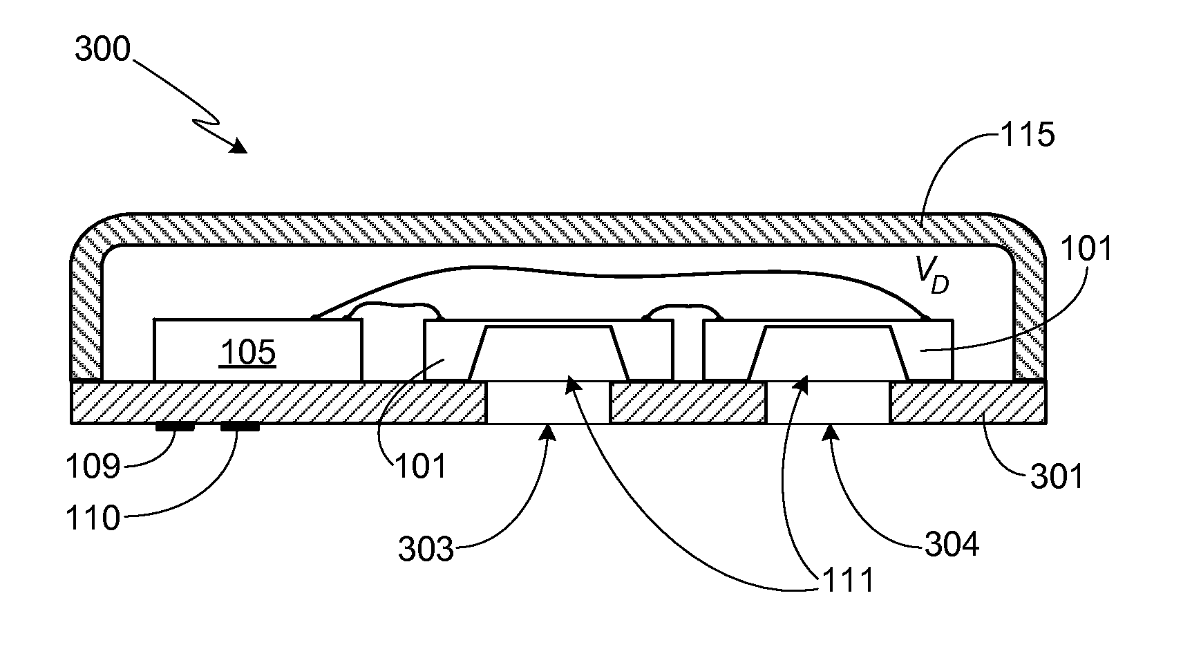
[0027]The present invention provides an assembly utilizing at least a pair of microelectromechanical system (MEMS) transducers, also referred to herein as cells. Although preferably the MEMS transducers are microphone transducers and the assembly comprises a high sensitivity microphone, it should be understood that in an assembly utilizing two or more MEMS transducers, the transducers may also be speaker transducers or ultrasonic transducers. It should be understood that identical element symbols used on multiple figures refer to the same component, or components of equal functionality. Additionally, the accompanying figures are only meant to illustrate, not limit, the scope of the invention and should not be considered to be to scale.

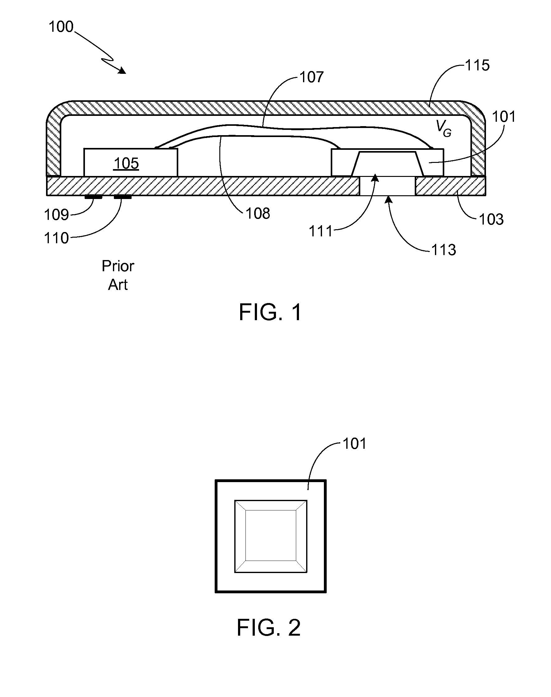
[0028]For comparison purposes, FIG. 1 provides a cross-sectional view of a MEMS microphone assembly 100 utilizing a single MEMS transducer in accordance with the prior art. As shown, MEMS microphone transducer 101 is attached to a substrate 103. Prefer...


PUM


Abstract

A transducer assembly utilizing at least two MEMS transducers is provided, the transducer assembly preferably defining either an omnidirectional or directional microphone. In addition to at least first and second MEMS transducers, the assembly includes a signal processing circuit electrically connected to the MEMS transducers, a plurality of terminal pads electrically connected to the signal processing circuit, and a transducer enclosure housing the first and second MEMS transducers. The MEMS transducers may be electrically connected to the signal processing circuit using either wire bonds or a flip-chip design. The signal processing circuit may be comprised of either a discrete circuit or an integrated circuit. The first and second MEMS transducers may be electrically connected in series or in parallel to the signal processing circuit. The first and second MEMS transducers may be acoustically coupled in series or in parallel.

Description

CROSS-REFERENCE TO RELATED APPLICATION[0001]This application claims the benefit of the filing date of U.S. Provisional Patent Application Ser. No. 61 / 471,123, filed Apr. 2, 2011, the disclosure of which is incorporated herein by reference for any and all purposes.FIELD OF THE INVENTION[0002]The present invention relates generally to microelectromechanical system (MEMS) transducers and, more particularly, to a transducer assembly designed to increase electro-acoustical sensitivity and thus electrical signal-to-noise (SNR) of the MEMS assembly by up to 6 dB.BACKGROUND OF THE INVENTION[0003]Miniature acoustic transducers, for example those fabricated using MEMS fabrication techniques, are used in a variety of applications such as stand-alone microphones, telephone handsets, cellular phones, hearing aids, and headsets. Typically such transducers, along with a microprocessor and interconnects, are mounted within a package that is designed to protect the transducer and associated componen...

Claims


Application Information

Patent Timeline
Patent Type & Authority Patents(United States)
IPC IPC(8): H04R1/40H04R3/00H04R19/04H04R19/00H04R1/30H04R1/28
CPCH04R1/2876H01L2924/3011H04R1/2807H04R1/406H04R1/30H01L2924/3025H04R19/005H04R3/005H01L2224/48137H01L2924/1461H04R19/04H01L2924/00
Inventor MICHEL, ALAN DEANMCATEER, JEFFREY PHILLIPBAUMHAUER, JR., JOHN CHARLES
Owner HARMAN INT IND INC
Why Eureka
Try Eureka