Image processing device and method and image display device

a processing device and image technology, applied in image enhancement, image analysis, instruments, etc., can solve the problem of unnatural processing in areas lacking edges, and achieve the effect of higher perceived resolution

Inactive Publication Date: 2014-08-12
MITSUBISHI ELECTRIC CORP
View PDF33 Cites 4 Cited by
  • Summary
  • Abstract
  • Description
  • Claims
  • Application Information

AI Technical Summary

Benefits of technology

[0014]An image processing device according to the present invention generates pixels having a variety of pixel values in textured areas, providing a higher perceived resolution in textured areas as well as other areas.

Problems solved by technology

When the values of pixels having values higher than the local average of the pixels around them are increased and the values of pixels having values lower than the local average of the pixels around them are decreased, however, the result of this processing may look unnatural in areas lacking edges.

Method used


Image

  • Image processing device and method and image display device
  • Image processing device and method and image display device
  • Image processing device and method and image display device

Examples


embodiment a1

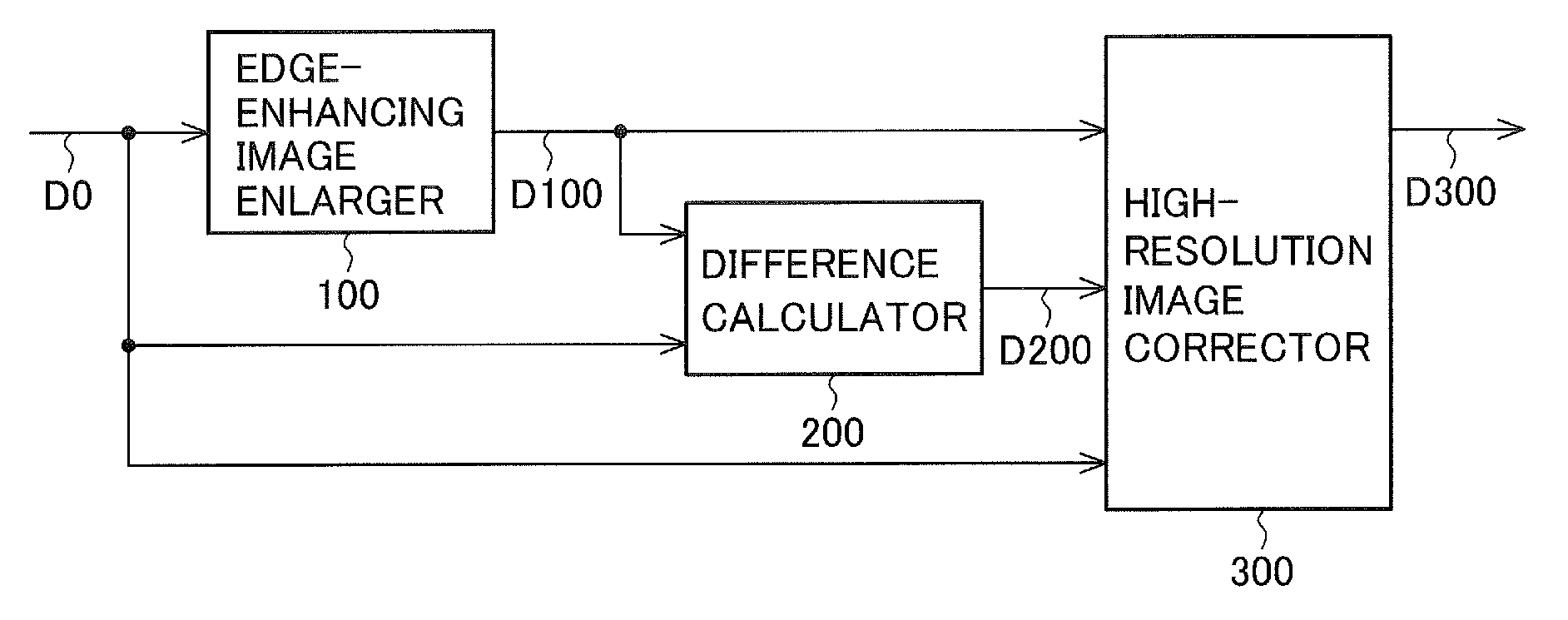
[0052]FIG. 1 is a block diagram of an image processing device in embodiment A1 of the invention. The image processing device in embodiment A1 has an edge-enhancing image enlarger 100, a difference calculator 200, and a high-resolution image corrector 300.

[0053]The edge-enhancing image enlarger 100 receives an input image D0 and outputs an edge-enhanced enlarged image D100 having more pixels than the input image D0. The edge-enhanced enlarged image D100 is an enlarged image in which edges in the input image D0 are enhanced. The enlarged image will also be referred to as a high-resolution image, and the input image as a low-resolution image.

[0054]The difference calculator 200 outputs difference data D200 expressing the difference between the input image D0 and the edge-enhanced enlarged image D100.

[0055]The high-resolution image corrector 300 corrects the edge-enhanced enlarged image D100 so as to partially or completely cancel out the differences expressed by the difference data D200...

embodiment a2

[0182]Like the image processing device in embodiment A1, the image processing device in embodiment A2 can be implemented by the structure shown in FIG. 1. The structure and operation of the high-resolution image corrector 300 are different, however, from those of the image processing device in embodiment A1. Like the image processing device in embodiment A1, the image processing device in embodiment A2 can also be used as part of an image display device.

[0183]FIG. 12 shows an example of the structure of the high-resolution image corrector 300 in embodiment A2.

[0184]The high-resolution image corrector 300 in FIG. 12 includes a diffusion coefficient calculator 301, a diffusion quantity calculator 302, an edge determiner 310, a texture determiner 320, a diffusion quantity corrector 400, and a subtractor 303b.

[0185]As the diffusion coefficient calculator 301 and diffusion quantity calculator 302, the same components may be used as described with reference to FIG. 5 in embodiment A1.

[01...

embodiment a3

[0262]The invention was described as being implemented by hardware in embodiment A1, but part or all of the structure shown in FIG. 1 may be implemented by software, that is, by a programmed computer. The image processing method in this case will be described with reference to FIGS. 15 to 18.

[0263]FIG. 15 shows a computing device used in the image processing method in embodiment A3, that is, a computing device (computer) that can be used as an image processing device in embodiment A3. The illustrated computing device includes an input interface U1A, a processor U1B, a program memory U1C, a data memory U1D, an output interface U1E, and a bus U1F that interconnects these components.

[0264]The processor U1B operates on an image input through the input interface U1A in accordance with a program stored in the program memory U1C. In the process of its operations, a variety of data are stored in the data memory U1D. The image created as a result of the process is output through the output i...


PUM


Abstract

An image processing device includes an edge-enhancing image enlarger that converts an input image to a high-resolution image with edge enhancement. A difference calculator determines differences between the high-resolution image and the input image. A high-resolution image corrector corrects the high-resolution image by diffusing the differences to pixels of the high-resolution image, thereby generating a corrected image in which edges are enhanced without image degradation in textured areas.

Description

BACKGROUND OF THE INVENTION[0001]1. Field of the Invention[0002]The present invention relates to an image processing device, an image processing method, an image display device, and a recording medium storing a program for executing the image display method.[0003]2. Description of the Related Art[0004]When an enlarged image is output, in conventional image processing, edge enhancement is carried out to remove blur.[0005]For example, in U.S. Patent Application Publication No. 2010 / 0134518, Moriya et al. disclose an image processing apparatus having a first image enlarging means that enlarges an input image and outputs a first enlarged image, a high-frequency component image generating means that extracts a high-frequency component of the input image and outputs a first high-frequency component image, a second image enlarging means that enlarges the first high-frequency component image and outputs a second enlarged image, a high-frequency component image processing means that extracts...

Claims


Application Information

Patent Timeline
Patent Type & Authority Patents(United States)
IPC IPC(8): G06K9/40G06T3/40G06T5/00G06T5/20
CPCG06T5/001G06T3/403G06T3/4053G06T5/003G06T5/20G06T2207/20192
Inventor MORIYA, SHOTAROYAMANAKA, SATOSHIYOSHII, HIDEKISUGINOHARA, HIDETSUGU
Owner MITSUBISHI ELECTRIC CORP
Why Eureka
Try Eureka