Dual bridge aircraft passenger boarding ramp assembly and method

a technology for passenger boarding ramps and aircraft, which is applied in the direction of passenger handling apparatus, vessel construction, special-purpose vessels, etc., can solve the problem that not all aircraft can be parked in the same position at the boarding gate, and achieve the effect of facilitating horizontal pivoting movement and horizontal pivoting movemen

Inactive Publication Date: 2014-08-19
KEITH CONSOLIDATED IND
View PDF20 Cites 6 Cited by
  • Summary
  • Abstract
  • Description
  • Claims
  • Application Information

AI Technical Summary

Benefits of technology

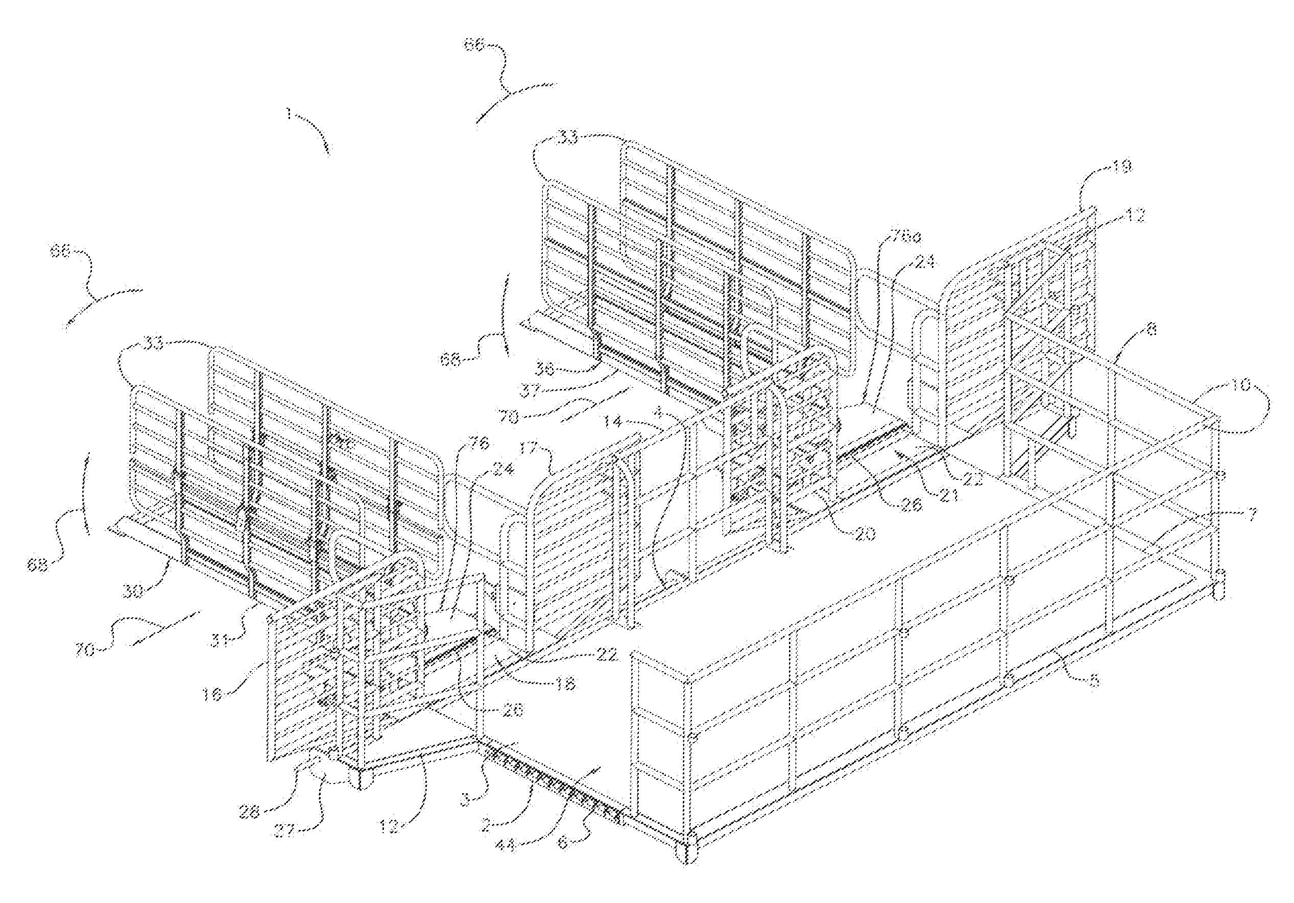
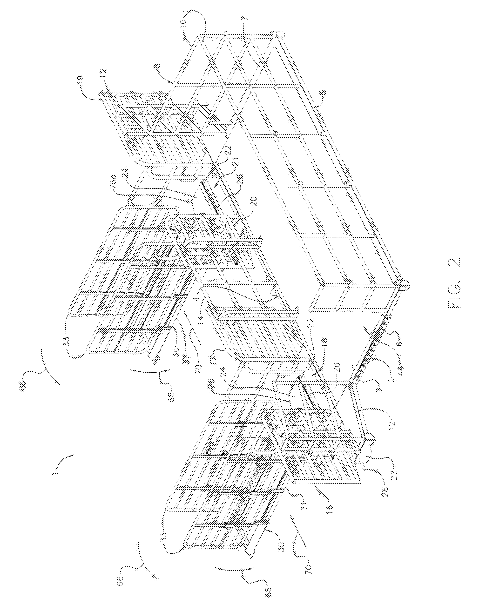
[0005]Illustrative embodiments of the disclosure are generally directed to a ramp assembly for deplaning passengers from and boarding passengers on an airplane. An illustrative embodiment of the ramp assembly includes a level deck, at least one bridge connector assembly carried by the level deck and at least one floating upper bridge carried by the at least one bridge connector assembly. The at least one bridge connector assembly facilitates horizontal pivoting movement, vertical pivoting movement and side-to-side movement of the at least one floating upper bridge relative to the level deck.
[0006]Illustrative embodiments of the disclosure are further generally directed to a passenger deplaning and boarding method. An illustrative embodiment of the passenger deplaning and boarding method includes providing a ramp assembly including a level deck, at least one bridge connector assembly carried by the level deck and at least one floating upper bridge carried by the at least one bridge connector assembly, the at least one bridge connector assembly facilitates horizontal pivoting movement, vertical pivoting movement and side-to-side movement of the at least one floating upper bridge relative to the level deck; parking an aircraft having at least one aircraft door; deploying the ramp assembly by aligning the at least one floating upper bridge of the ramp assembly with the at least one aircraft door; supporting the at least one floating upper bridge in the at least one aircraft door of the aircraft; deplaning a first group of passengers from the aircraft using the ramp assembly; and boarding a second group of passengers from the aircraft using the ramp assembly.

Problems solved by technology

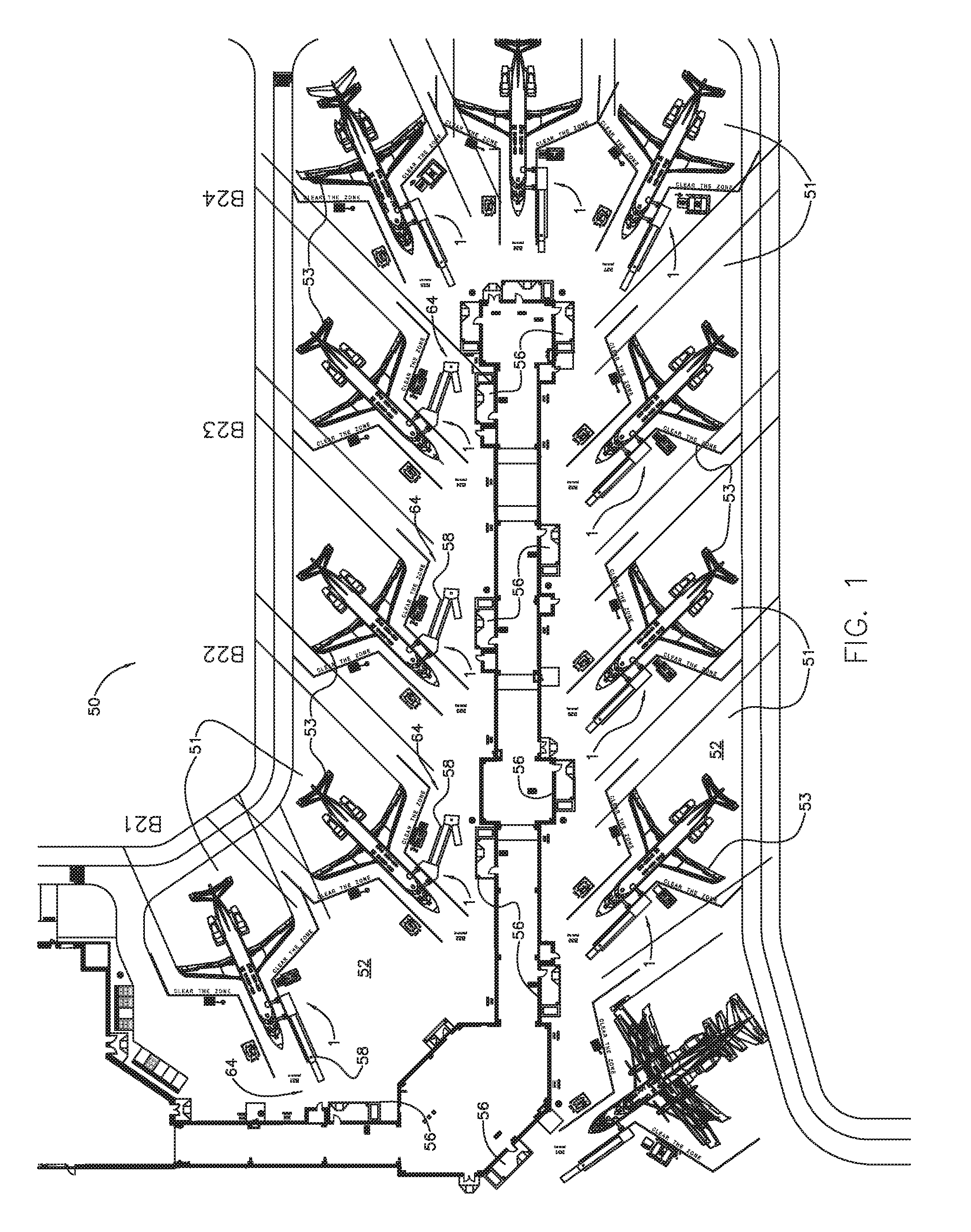
Because of the varying lengths of aircraft fuselages and positioning of ground support equipment, however, not all aircraft can be parked in the same position at the boarding gate.

Method used


Image

  • Dual bridge aircraft passenger boarding ramp assembly and method
  • Dual bridge aircraft passenger boarding ramp assembly and method
  • Dual bridge aircraft passenger boarding ramp assembly and method

Examples


Embodiment Construction

[0015]The following detailed description is merely exemplary in nature and is not intended to limit the described embodiments or the application and uses of the described embodiments. As used herein, the word “exemplary” or “illustrative” means “serving as an example, instance, or illustration.” Any implementation described herein as “exemplary” or “illustrative” is not necessarily to be construed as preferred or advantageous over other implementations. All of the implementations described below are exemplary implementations provided to enable persons skilled in the art to practice the disclosure and are not intended to limit the scope of the appended claims. Moreover, the illustrative embodiments described herein are not exhaustive and embodiments or implementations other than those which are described herein and which fall within the scope of the appended claims are possible. Furthermore, there is no intention to be bound by any expressed or implied theory presented in the precedi...


PUM


Abstract

A ramp assembly for deplaning passengers from and boarding passengers on an airplane includes a level deck, at least one bridge connector assembly carried by the level deck and at least one floating upper bridge carried by the at least one bridge connector assembly. The at least one bridge connector assembly facilitates horizontal pivoting movement, vertical pivoting movement and side-to-side movement of the at least one floating upper bridge relative to the level deck. A passenger deplaning and boarding method is also disclosed.

Description

CROSS-REFERENCE TO RELATED APPLICATIONS[0001]This application claims the benefit of U.S. provisional application No. 61 / 964,051, filed Dec. 23, 2013 and entitled “DUAL BRIDGE AIRCRAFT PASSENGER BOARDING RAMP”, which provisional application is incorporated by reference herein in its entirety.FIELD OF THE INVENTION[0002]Illustrative embodiments of the disclosure generally relate to structures and methods for deplaning passengers from and boarding passengers onto aircraft. More particularly, illustrative embodiments of the disclosure relate to a dual bridge aircraft passenger boarding ramp assembly having at least one adjustable bridge to accommodate various types of aircraft in the boarding of passengers onto the aircraft and a passenger deplaning and boarding method.BACKGROUND OF THE INVENTION[0003]Conventional boarding and deplaning of passengers onto and from a commercial type aircraft at a boarding gate of an airport may be accomplished using a passenger boarding bridge or jet bri...

Claims


Application Information

Patent Timeline
Patent Type & Authority Patents(United States)
IPC IPC(8): E01D15/00B64F1/305
CPCB64F1/3055
Inventor KEITH, WILLIAM FLOYDKEITH, CHRISTA
Owner KEITH CONSOLIDATED IND
Why Eureka
Try Eureka