Plasma arc torch having multiple operating modes
a plasma torch and operating mode technology, applied in plasma welding apparatus, gas-filled discharge tubes, manufacturing tools, etc., can solve the problems of not being able to recover heat or generate hydrogen, the plasma reactor is not designed for separating gas, and the addition of air to the plasma reactor completely defeats the sole purpose of current research for generating hydrogen via electrolysis or plasma or a combination of both
- Summary
- Abstract
- Description
- Claims
- Application Information
AI Technical Summary
Problems solved by technology
Method used
Image
Examples
example 1
Black Liquor
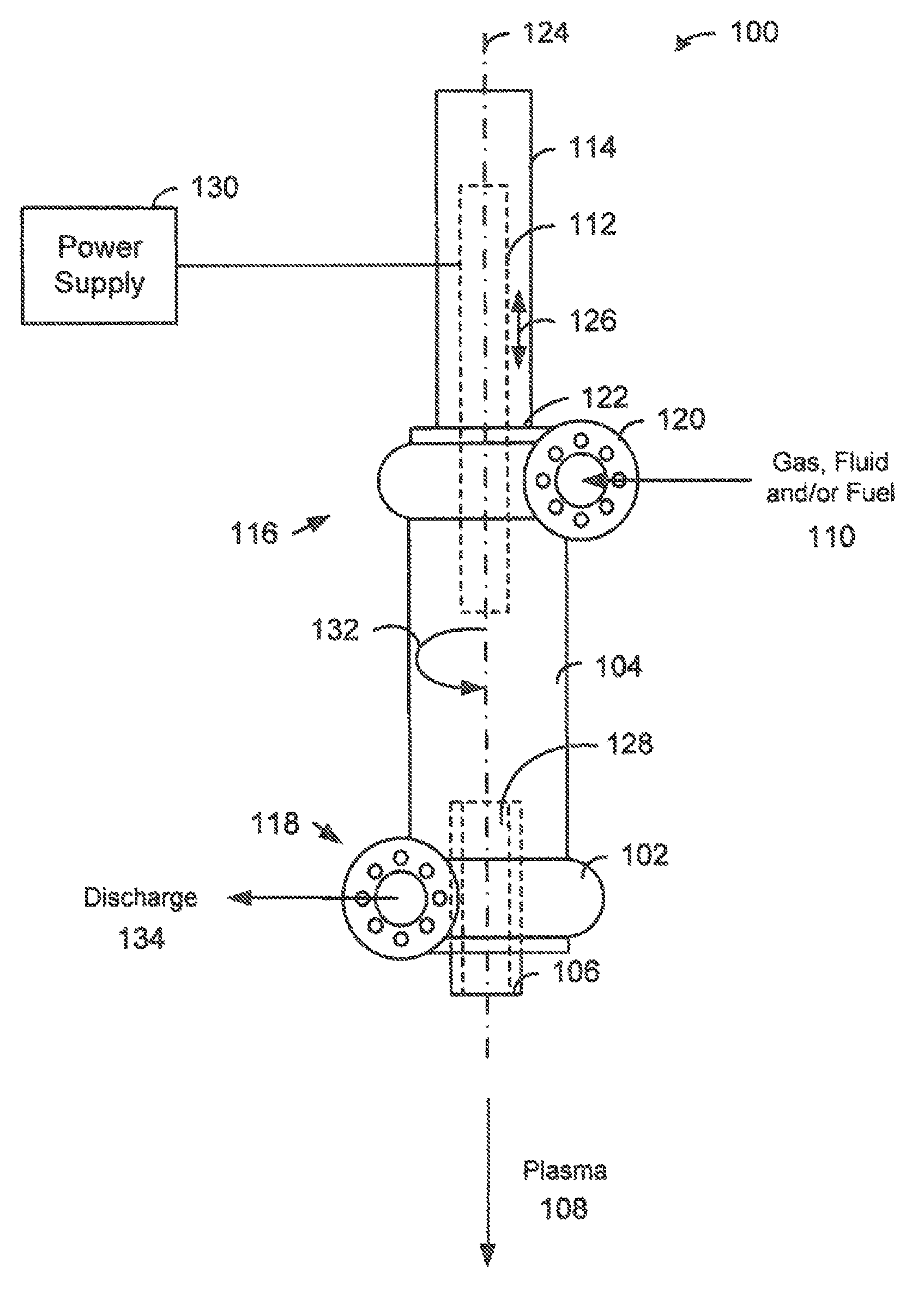
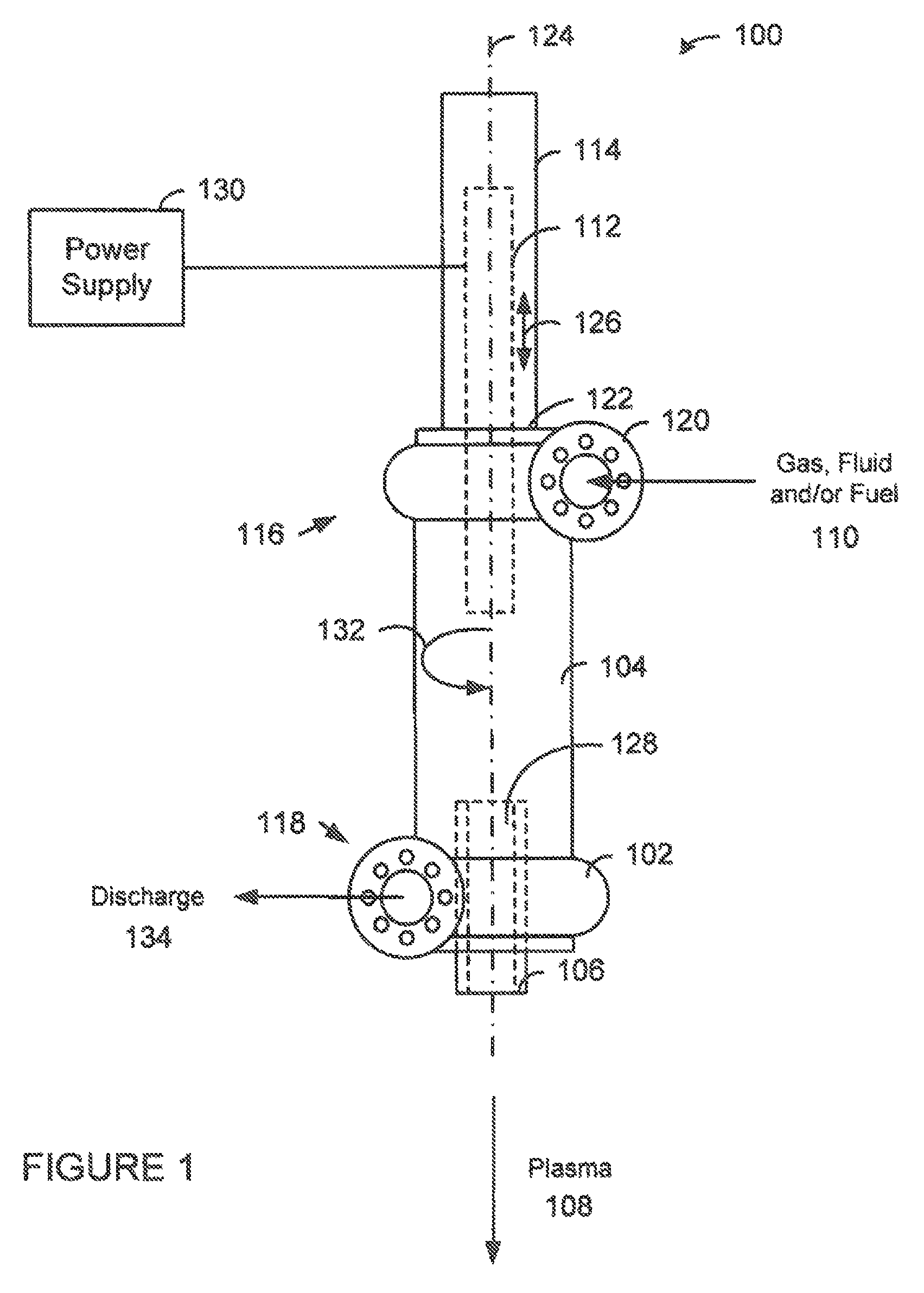
[0056]Now referring to FIG. 6, a cross-sectional view of a Solid Oxide Plasma Arc Torch System 600 in accordance with another embodiment of the present invention is shown. A plasma arc torch 100 is connected to the cell 500 via an eductor 602. Once again the cell 500 was filled with a baking soda and water solution. A pump was connected to the first volute 31 of the plasma arc torch 100 via a 3-way valve 604 and the eductor 602. The eductor 602 pulled a vacuum on the cell 500. The plasma exiting from the plasma arc torch 100 dramatically increased in size. Hence, a non-condensable gas B was produced within the cell 500. The color of the arc within the plasma arc torch 100 when viewed through the sightglass 33 changed colors due to the gases produced from the HiTemper™ cell 500. Next, the 3-way valve 604 was adjusted to allow air and water F to flow into the first volute 31 of plasma arc torch 100. The additional mass flow increased the plasma G exiting from the plasma ar...
example 2
Arcwhirl® Plasma Torch Attached to Solid Oxide Cell
[0061]Referring now to FIG. 7, a cross-sectional view of a Solid Oxide Plasma Arc Torch System 700 in accordance with another embodiment of the present invention is shown. A plasma arc torch 100 is connected to the cell 500 via an eductor 602. Once again the cell 500 was filled with a baking soda and water solution. Pump 23 recirculates the baking soda and water solution from the outlet 416 of the hollow electrode 504 to the inlet 408 of the cell 500. A pump 22 was connected to the first volute 31 of the plasma arc torch 100 via a 3-way valve 604 and the eductor 602. An air compressor 21 was used to introduce air into the 3-way valve 604 along with water F from the pump 22. The pump 22 was turned on and water F flowed into the first volute 31 of the plasma arc torch 100 and through a full view site glass 33 and exited the torch 30 via a second volute 34. The plasma arc torch 100 was started by pushing a carbon cathode rod (−NEG) 32 ...
example 3
Phosphogypsum Pond Water
[0065]The phosphate industry has truly left a legacy in Florida, Louisiana and Texas that will take years to cleanup—gypsum stacks and pond water. On top of every stack is a pond. Pond water is recirculated from the pond back down to the plant and slurried with gypsum to go up the stack and allow the gypsum to settle out in the pond. This cycle continues and the gypsum stack increases in height. The gypsum is produced as a byproduct from the ore extraction process.
[0066]There are two major environmental issues with every gyp stack. First, the pond water has a very low pH. It cannot be discharged without neutralization. Second, the phosphogypsum contains a slight amount of radon. Thus, it cannot be used or recycled to other industries. The excess water in combination with ammonia contamination produced during the production of P2O5 fertilizers such as diammonium phosphate (“DAP”) and monammonium phosphate (“MAP”) must be treated prior to discharge. The excess ...
PUM
| Property | Measurement | Unit |
|---|---|---|
| temperature | aaaaa | aaaaa |
| temperature | aaaaa | aaaaa |
| temperature | aaaaa | aaaaa |
Abstract
Description
Claims
Application Information
 - R&D
- Intellectual Property
- Life Sciences
- Materials
- Tech Scout
- Unparalleled Data Quality
- Higher Quality Content
- 60% Fewer Hallucinations
Browse by: Latest US Patents, China's latest patents, Technical Efficacy Thesaurus, Application Domain, Technology Topic, Popular Technical Reports.
© 2025 PatSnap. All rights reserved.Legal|Privacy policy|Modern Slavery Act Transparency Statement|Sitemap|About US| Contact US: help@patsnap.com


