
Motor control center and communication system therefor

a technology of communication system and motor control center, which is applied in the direction of process and machine control, furniture parts, instruments, etc., can solve the problems of system malfunction, loss of production, and wide variety of problems

Active Publication Date: 2014-08-19
EATON INTELLIGENT POWER LTD
View PDF15 Cites 8 Cited by
  • Summary
  • Abstract
  • Description
  • Claims
  • Application Information

AI Technical Summary

Benefits of technology

This solution maintains system integrity and reduces downtime by keeping the communication module fixed within the motor control center, allowing for easy access and configuration, while preventing electromagnetic interference, thus minimizing production losses.

Problems solved by technology

This can cause a wide variety of problems.
For example, when a bucket including the communication module is unplugged from the motor control center, the computerized controlling program loses the connection which may cause a malfunction of the system.
Among other disadvantages, are lost production, due to downtime to address the system failure.

Method used


Image

  • Motor control center and communication system therefor
  • Motor control center and communication system therefor
  • Motor control center and communication system therefor

Examples


example

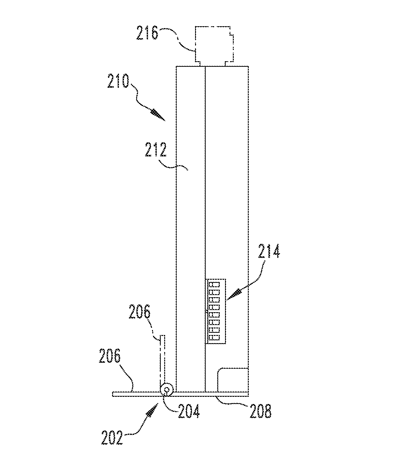
[0040]By way of a non-limiting example, which is provided solely for purposes of illustration and is not intended to limit the scope of the disclosed concept, in FIG. 4, an Ethernet cable 240 extends outwardly (e.g., to the left from the perspective of FIG. 4) from the communication module 210 and, in particular, from a connection with Ethernet connector 214 (shown in simplified form in FIGS. 8 and 9), and into wireway 230. A 24 VDC control circuit wire 242 (shown in simplified form in phantom line drawing in FIG. 4; also shown schematically in FIG. 5) also extends (e.g., to the left from the perspective of FIG. 4) toward and into the same wireway 230. A third cable, which in the example shown and described herein is a 120 VAC control circuit wire 244, extends in the opposite direction (e.g., to the right from the perspective of FIG. 4) into and through wireway 232 on the opposite side of the compartment 112.

[0041]Accordingly, it will be appreciated that the disclosed communication ...


PUM


Abstract

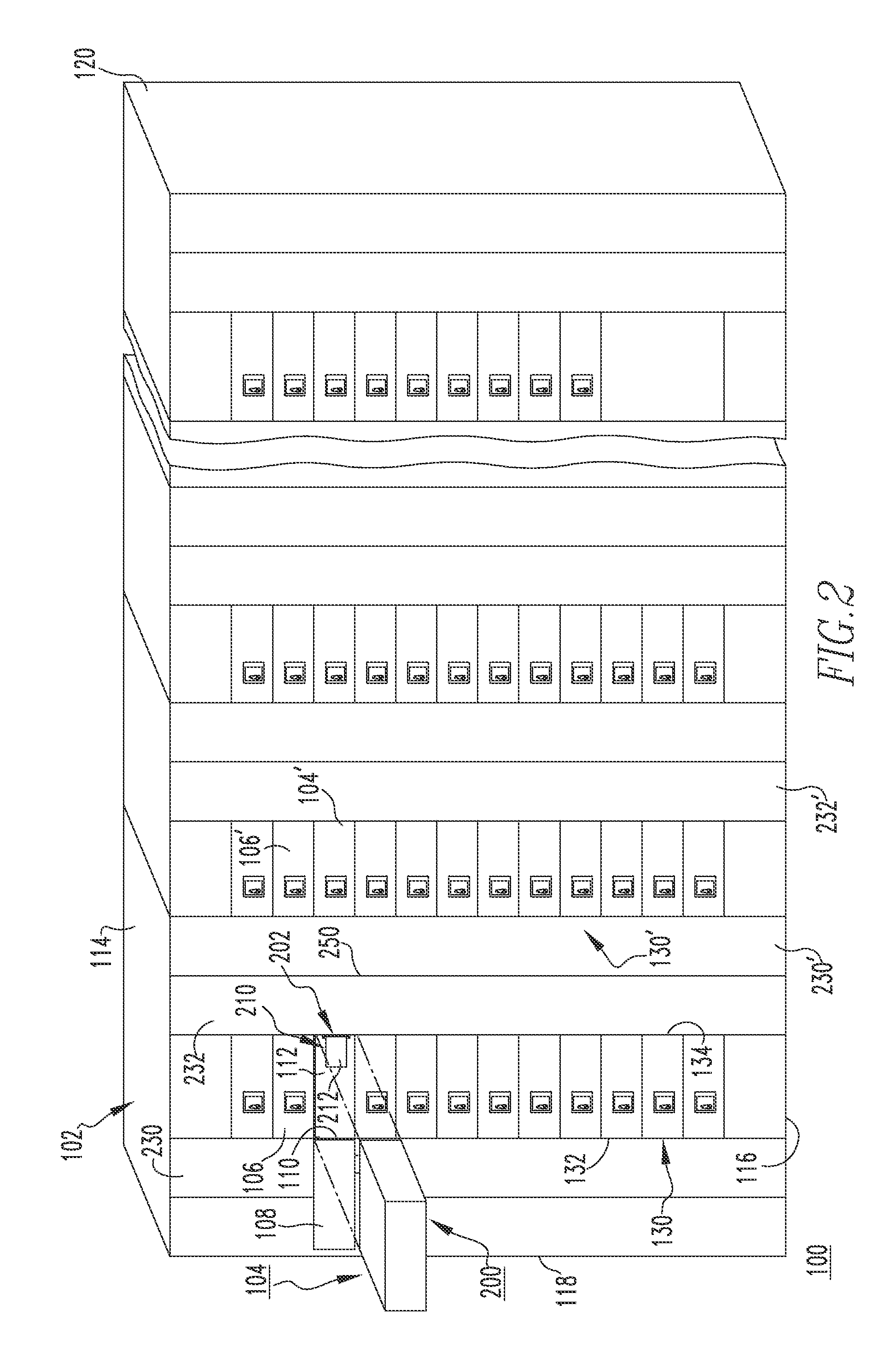
A communication system is provided for a motor control center. The motor control center includes an enclosure and a plurality of subunits. The enclosure comprises a framework for dividing the enclosure into a plurality of compartments. The subunits are removably disposed within the compartments. The communication system includes a mounting bracket fixedly attached to the framework, within a corresponding one of the compartments, and a communication module mounted on the mounting bracket. The communication module includes a housing and a number of features such as, for example and without limitation, a DIP switch and electrical connector(s), disposed on the housing. Accordingly, when the subunit is removed from the compartment, the communication module remains, fixed to the enclosure framework. The mounting bracket includes a hinge that allows the communication module to pivot with respect to the compartment to provide access to the features.

Description

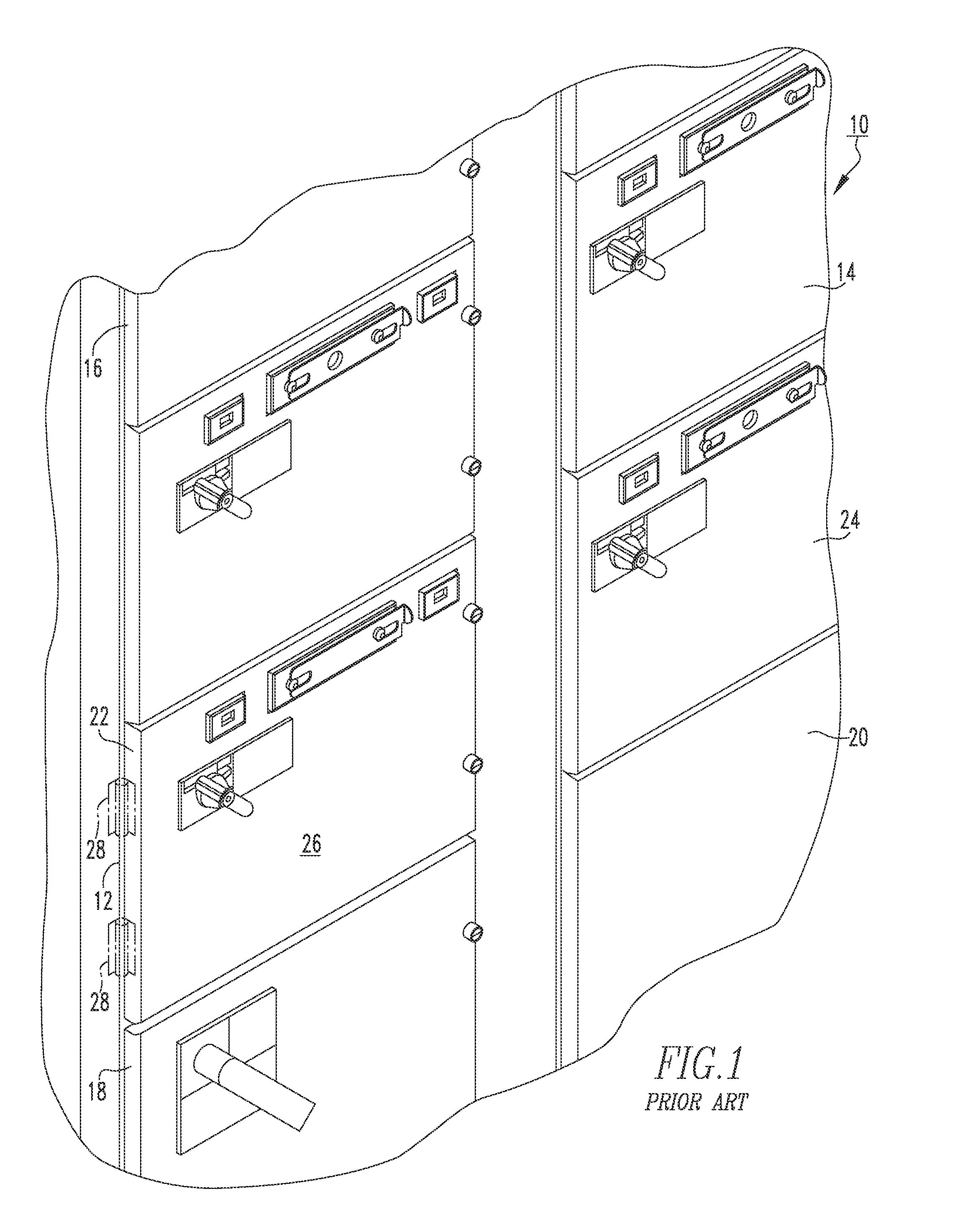
BACKGROUND[0001]1. Field[0002]The disclosed concept relates generally to motor control systems, and more particularly, to motor control centers. The disclosed concept also relates to communication systems for motor control centers.[0003]2. Background Information[0004]Motor control centers are used, for example, in some commercial and industrial applications to distribute electrical power to a variety of loads (e.g., without limitation, relatively high power electrical motors, pumps, and other loads).[0005]FIG. 1, for example, shows a portion of a motor control center 10. The motor control center 10 includes a multi-compartment enclosure 12 for receiving a plurality of motor control modules or subunits 14,16,18,20,22,24, commonly referred to as “buckets”. Typically, each bucket (see, e.g., bucket 22 of FIG. 1) is a removable, pull-out subunit that has, or is installed behind, a door 26. The door 26 is preferably coupled to the enclosure 12 by hinges 28 (shown in phantom line drawing ...

Claims


Application Information

Patent Timeline
Patent Type & Authority Patents(United States)
IPC IPC(8): H02B11/12H02B1/04H02B1/26H02H5/04H02H7/09
CPCH02B11/12H02B1/04H02H5/04H02H7/09H02B1/306H02B1/36
Inventor FELDMEIER, GERALD RAYMONDYEE, EDGARMORRIS, ROBERT ALLAN
Owner EATON INTELLIGENT POWER LTD
Learn More