
Steam sterilizer

a sterilizer and steam technology, applied in the field of compact sterilizers, can solve the problems of difficult handling and the heat of metal trays and cassettes is extremely high

Active Publication Date: 2014-08-26
AMERICAN STERILIZER CO
View PDF19 Cites 8 Cited by
  • Summary
  • Abstract
  • Description
  • Claims
  • Application Information

AI Technical Summary

Benefits of technology

The present invention is a sterilizer that can be used to sterilize medical instruments and devices. This sterilizer uses saturated steam at a specific temperature to effectively kill bacteria and other harmful microbes. Additionally, the sterilizer can be portable, meaning it can be easily moved and sterilize instruments in various locations. The sterilizer has a cassette with an inner container that defines a sterilizing chamber, with an outer shell made of insulating material. The container is made of metal sheets and can be easily sterilized itself. The technical effects of this invention are improved sterilization efficiency, portability, and ease of use.

Problems solved by technology

As a result of the exposure to the steam, the metal trays and cassettes become extremely hot and difficult to handle following a sterilization process.

Method used


Image

  • Steam sterilizer
  • Steam sterilizer
  • Steam sterilizer

Examples


Embodiment Construction

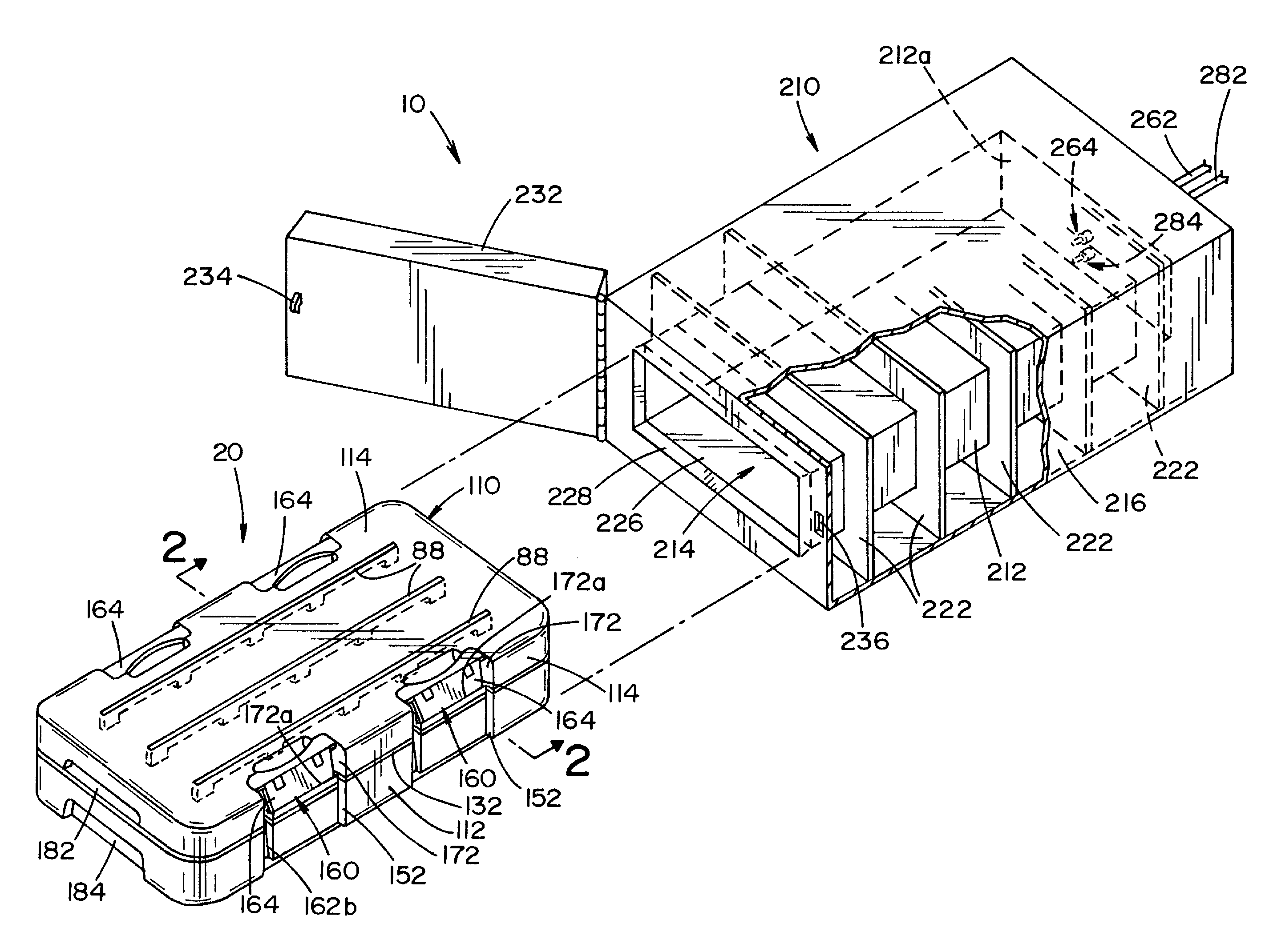
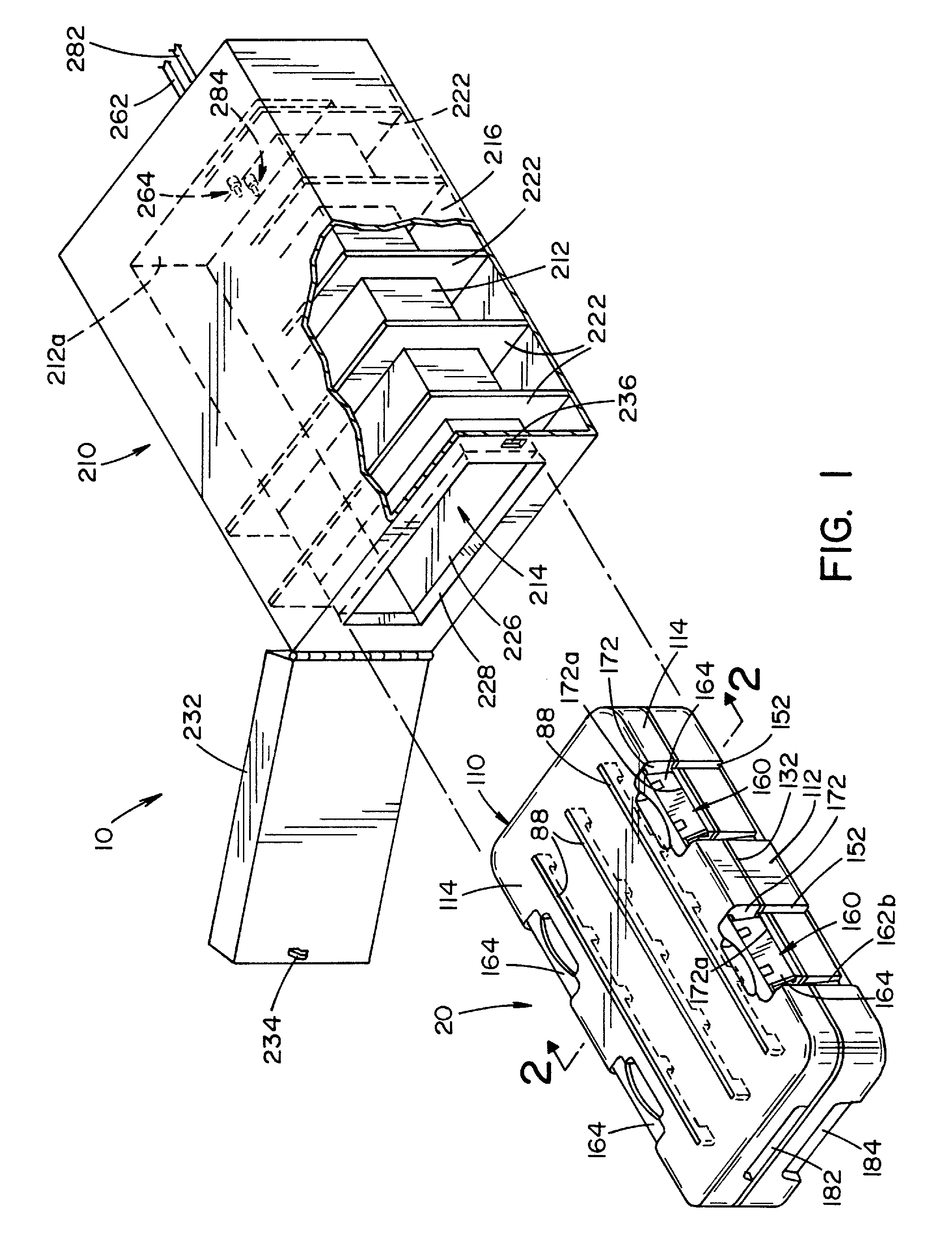
[0035]Referring now to the drawings wherein the showing is for the purpose of illustrating a preferred embodiment of the invention only and not for the purpose of limiting same, FIG. 1 shows a cassette 20 and receiver unit 210 that form part of a sterilizer 10, illustrating a preferred embodiment of the present invention. Cassette 20 is comprised of an inner, rigid container 30 encased within a shell 110 of an insulating material.

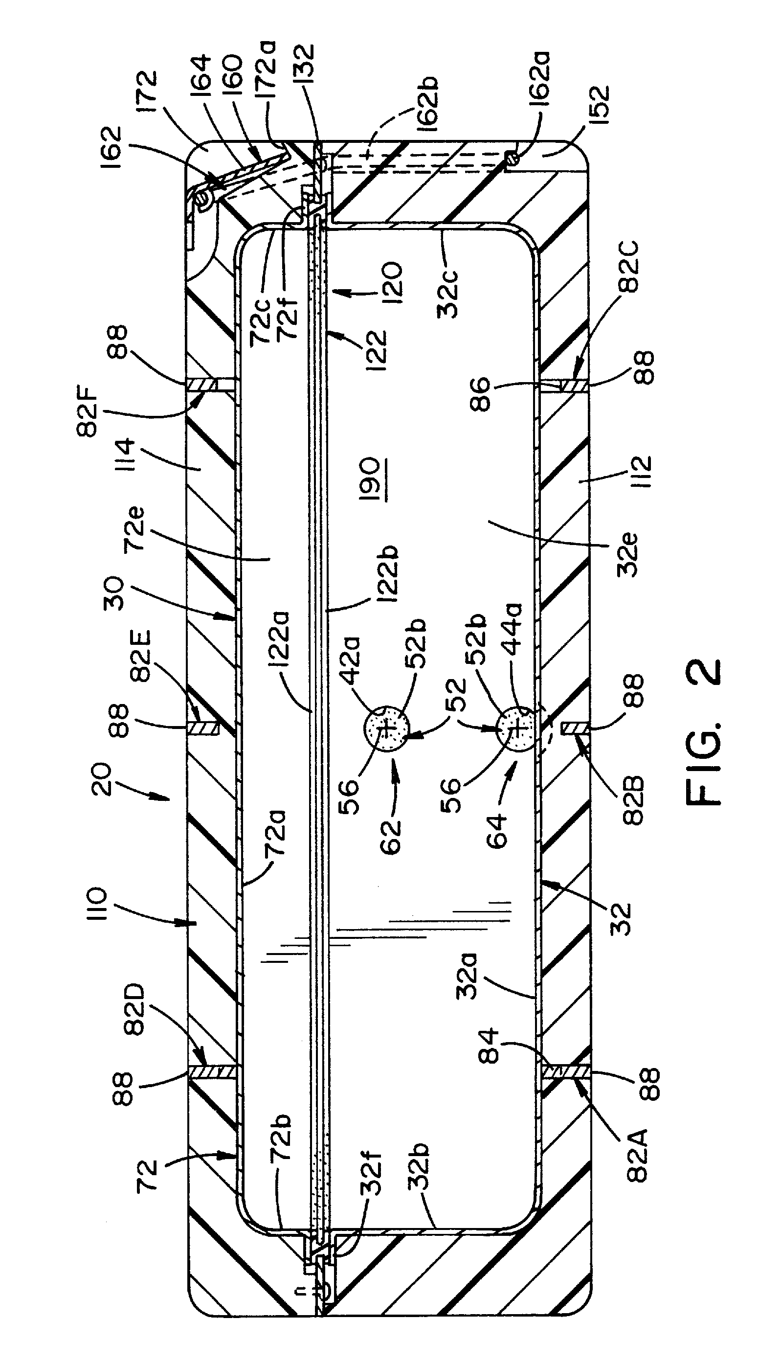
[0036]Container 30, best seen in FIG. 7, is comprised of a tray section 32 and a lid section 72. Tray section 32 is generally rectangular in shape and has a flat, planar bottom wall 32a, spaced-apart planar, parallel side walls 32b, 32c, a front wall 32d and a back wall 32e. Bottom wall 32a, side walls 32b, 32c, front wall 32d and back wall 32e define a generally rectangular structure having an opened upper end. A flange 32f extends outwardly from the upper edges of side walls 32b, 32c and front and back walls 32d, 32e and defines an upward-facing, planar t...


PUM

PropertyMeasurementUnit
insulatingaaaaaaaaaa
shapeaaaaaaaaaa
temperatureaaaaaaaaaa

Abstract

A sterilizer having a cassette for holding metal instruments or medical devices. The cassette includes a metallic container that defines a sterilization chamber. The container has at least one outer surface. A plurality of spaced-apart, elongated rails extend along the at least one outer surface of the container. Each of the rails includes a free, longitudinal edge wherein the edges of the rails lie in a first plane. An insulating shell encases the metallic container and the plurality of rails. An outer surface of the insulating shell lies in the first plane. A receiving unit includes a housing having an outer surface and an inner surface. The inner surface engages the edges of the rails and the outer surface of the insulating shell when the cassette is disposed within the inner housing. A plurality of spaced-apart elongated ribs extends along the outer surface of the housing.

Description

RELATED APPLICATIONS[0001]This application claims the benefit of U.S. Provisional Application No. 61 / 684,355, filed Aug. 17, 2012, which is fully incorporated herein by reference.FIELD OF THE INVENTION[0002]The present invention relates generally to sterilizers and, more particularly, to a compact steam sterilizer for sterilizing medical instruments and medical devices.BACKGROUND OF THE INVENTION[0003]It is known to sterilize small sets of medical instruments or medical devices in metal trays or metal cassettes. One requirement for steam sterilizers that sterilize medical instruments and medical equipment is that the instrument or device to be sterilized be subject to saturated steam at a prescribed temperature for a prescribed period of time. As a result of the exposure to the steam, the metal trays and cassettes become extremely hot and difficult to handle following a sterilization process.[0004]The present invention relates to a steam sterilizer for sterilizing medical instrument...

Claims


Application Information

Patent Timeline
Patent Type & Authority Patents(United States)
IPC IPC(8): A61L2/00B65D25/00A47J39/00B65D1/40A24F27/00A61L2/07
CPCA61L2/07A61L2202/24A61L2202/182
Inventor BACIK, MICHAEL ABUCZYNSKI, PETER JZELINA, FRANCIS JROBERTSON, JEFFREY C
Owner AMERICAN STERILIZER CO
Learn More