
Electrothermal wing ice protection system

a technology of electro-thermal wing and ice protection system, which is applied in the direction of de-icing equipment, transportation and packaging, and energy-saving board measures, etc. it can solve the problems of inflexibility of existing electro-thermal wing de-icing systems, flight delays and flight hazards, and inconvenient installation and maintenance of aircra

Active Publication Date: 2014-09-02
ULTRA ELECTRONICS TCS
View PDF15 Cites 4 Cited by
  • Summary
  • Abstract
  • Description
  • Claims
  • Application Information

AI Technical Summary

Benefits of technology

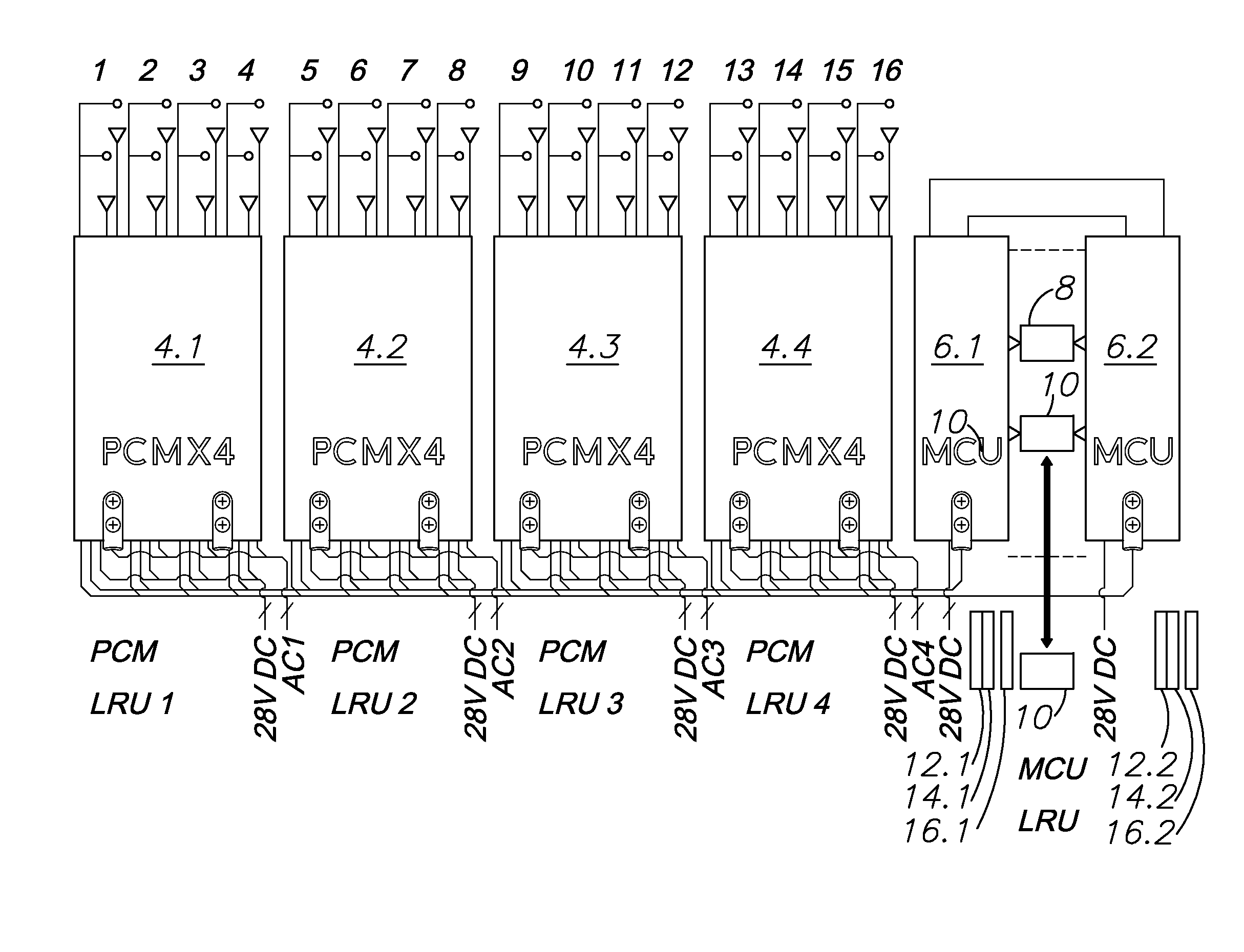
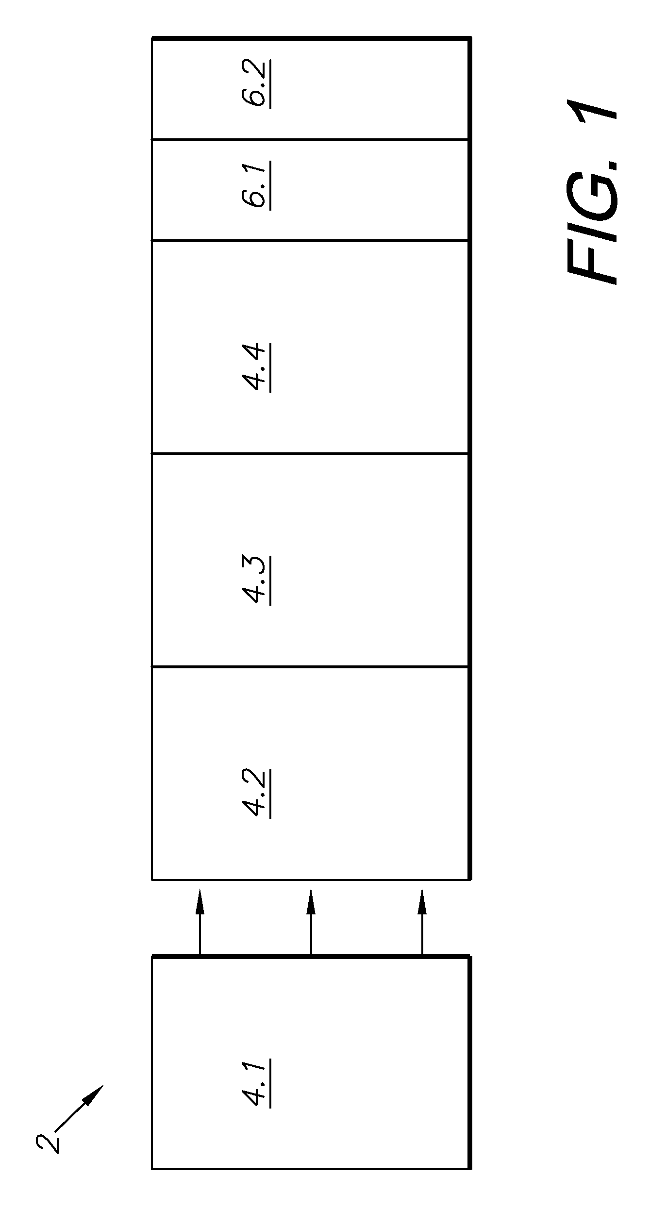
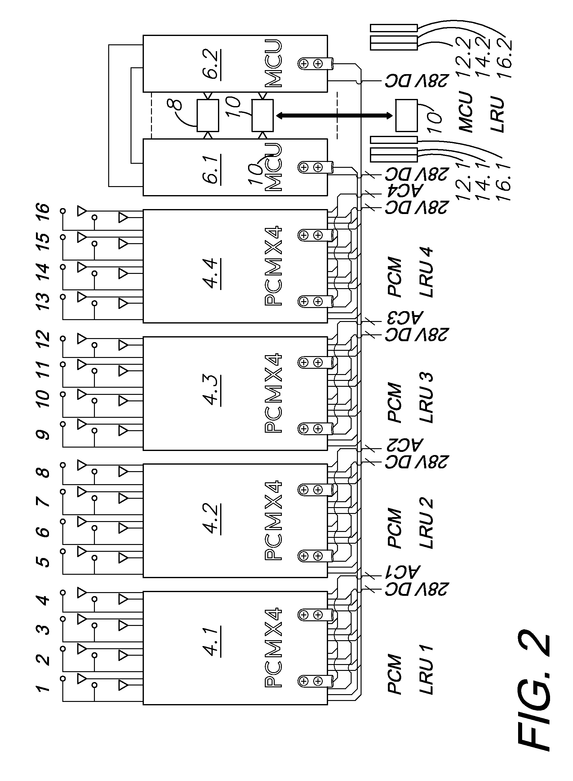
The present invention is about a device that controls the power used to heat and de-ice an aircraft's wings. It consists of multiple control modules that work together to manage the electrical power needed for the process. The device is designed to be scalable and organized, with a main control unit that manages the overall power distribution for the wings. The technical effect is an efficient and effective system for protecting and de-icing aircraft wings.

Problems solved by technology

Ice buildup on the wings of aircraft can cause flight delays and flight hazards.
Many aircraft have wing de-icing systems built into the craft, but often these systems are inefficient or under-equipped for the aircraft into which they are installed.
Existing electro-thermal wing de-icing systems are less flexible, unreliable, and inefficient.

Method used


Image

  • Electrothermal wing ice protection system
  • Electrothermal wing ice protection system
  • Electrothermal wing ice protection system

Examples


Embodiment Construction

[0020]I. Introduction and Environment

[0021]As required, detailed aspects of the present invention are disclosed herein, however, it is to be understood that the disclosed aspects are merely exemplary of the invention, which may be embodied in various forms. Therefore, specific structural and functional details disclosed herein are not to be interpreted as limiting, but merely as a basis for the claims and as a representative basis for teaching one skilled in the art how to variously employ the present invention in virtually any appropriately detailed structure.

[0022]Certain terminology will be used in the following description for convenience in reference only and will not be limiting. For example, up, down, front, back, right and left refer to the invention as orientated in the view being referred to. The words, “inwardly” and “outwardly” refer to directions toward and away from, respectively, the geometric center of the aspect being described and designated parts thereof. Forwardl...


PUM


Abstract

An electro-thermal wing ice protection solution controller for managing and controlling electrical power generated to heat and de-ice the wing of an aircraft. The system is comprised of a number of power control modules (PCMs) and at least one master control unit (MCU). These elements can be stacked together and mounted into rack systems in order to provide scalable organized power distribution for a wing de-icing and ice protection system.

Description

CROSS-REFERENCE TO RELATED APPLICATION[0001]This application claims priority in U.S. Provisional Patent Application Ser. No. 61 / 489,141, filed May 23, 2011, which is incorporated herein by reference.BACKGROUND OF THE INVENTION[0002]1. Field of the Invention[0003]The present invention relates generally to a system for electrically heating and de-icing the wing of an airplane, and more particularly to a system and method for providing power and control through a wing de-icing system in an airplane using stackable, scalable elements.[0004]2. Description of the Related Art[0005]Ice buildup on the wings of aircraft can cause flight delays and flight hazards. Typical wing de-icing systems include multiple individual heating elements spaced about the wing surface of the aircraft. These heating elements are typically powered by electricity. Many aircraft have wing de-icing systems built into the craft, but often these systems are inefficient or under-equipped for the aircraft into which the...

Claims


Application Information

Patent Timeline
Patent Type & Authority Patents(United States)
IPC IPC(8): B64D15/12B64D15/14
CPCB64D15/12Y02T50/54Y02T50/50
Inventor STONESTREET, II, ARLIE D.KRAUS, JR., HAROLD G.GENEREUX, DARIN E.
Owner ULTRA ELECTRONICS TCS
Learn More