Method and apparatus for meniscal repair

a meniscus and repair method technology, applied in the field of surgical methods and equipment, can solve the problems of affecting the normal movement of the knee joint, and the tissue itself is a fibrous structure that is no

Active Publication Date: 2014-09-09
LINVATEC
View PDF80 Cites 15 Cited by
  • Summary
  • Abstract
  • Description
  • Claims
  • Application Information

AI Technical Summary

Benefits of technology

[0030]a leading cleat, the suture being connected to the leading cleat so that the leading cleat can restrict retrograde movement of the suture relative to the leading cleat;
[0055]a leading cleat, the suture being connected to the leading cleat so that the leading cleat can restrict retrograde movement of the suture relative to the leading cleat;

Problems solved by technology

The meniscus is frequently damaged (e.g., torn) as the result of injury and / or accident.
A damaged meniscus can impede proper motion of the knee joint and cause pain, among other problems.
A major challenge in repairing a torn meniscus is the fact that the tissue itself is a fibrous structure that is not uniformly vascular.
Another significant challenge in repairing a torn meniscus is that the size and shape of the tears vary, making the reduction and apposition of the torn tissue difficult to accomplish.
Without proper apposition and stability, torn meniscal tissue will not heal properly.
The specific issues and challenges associated with the aforementioned all-suture inside-out and outside-in repair techniques are centered primarily on issues relating to the “user interface” and to the “tethering” of the meniscus to the knee capsule.
More particularly, the “user interface” issues generally relate to the technical demands required in the operating room: the skill of the surgeon and the number of assistants required to safely pass the needle and suture from the anterior portion of the meniscus through the posterior portion of the meniscus and exit out through the posterior / medial aspect of the knee joint (i.e., the so-called “inside-out” technique); or the passing of a needle and suture from the medial aspect of the exterior of the knee into the knee joint, through the meniscus, the retrieval and re-insertion back into the meniscus, and then passage back out through the capsule to the medial aspect of the knee (i.e., the so-called “outside-in” technique).
The aforementioned tethering issues relate to more recent concerns about fixating suture over the knee capsule and thereby “tethering” the meniscus to the knee capsule, since evidence suggests that such tethering of the meniscus to the knee capsule may interfere with the normal biomechanics of the meniscus (e.g., load and force distribution, etc.).
However, these materials are quite hard when first inserted into the meniscus and, in use, were found to degrade or bioabsorb much more slowly than anticipated.
Clinical use and follow-up have demonstrated the inherent risks associated with the use of such tack-like implants within the knee joint, as numerous published studies have reported device failure which can lead to tear reformation, loose implants within the knee joint and articular cartilage damage.
Furthermore, it can be challenging for the surgeon to adequately address various tear shapes and sizes using these tack-like implants.
However, none of these systems have been found to be completely satisfactory.

Method used


Image

  • Method and apparatus for meniscal repair
  • Method and apparatus for meniscal repair
  • Method and apparatus for meniscal repair

Examples


Embodiment Construction

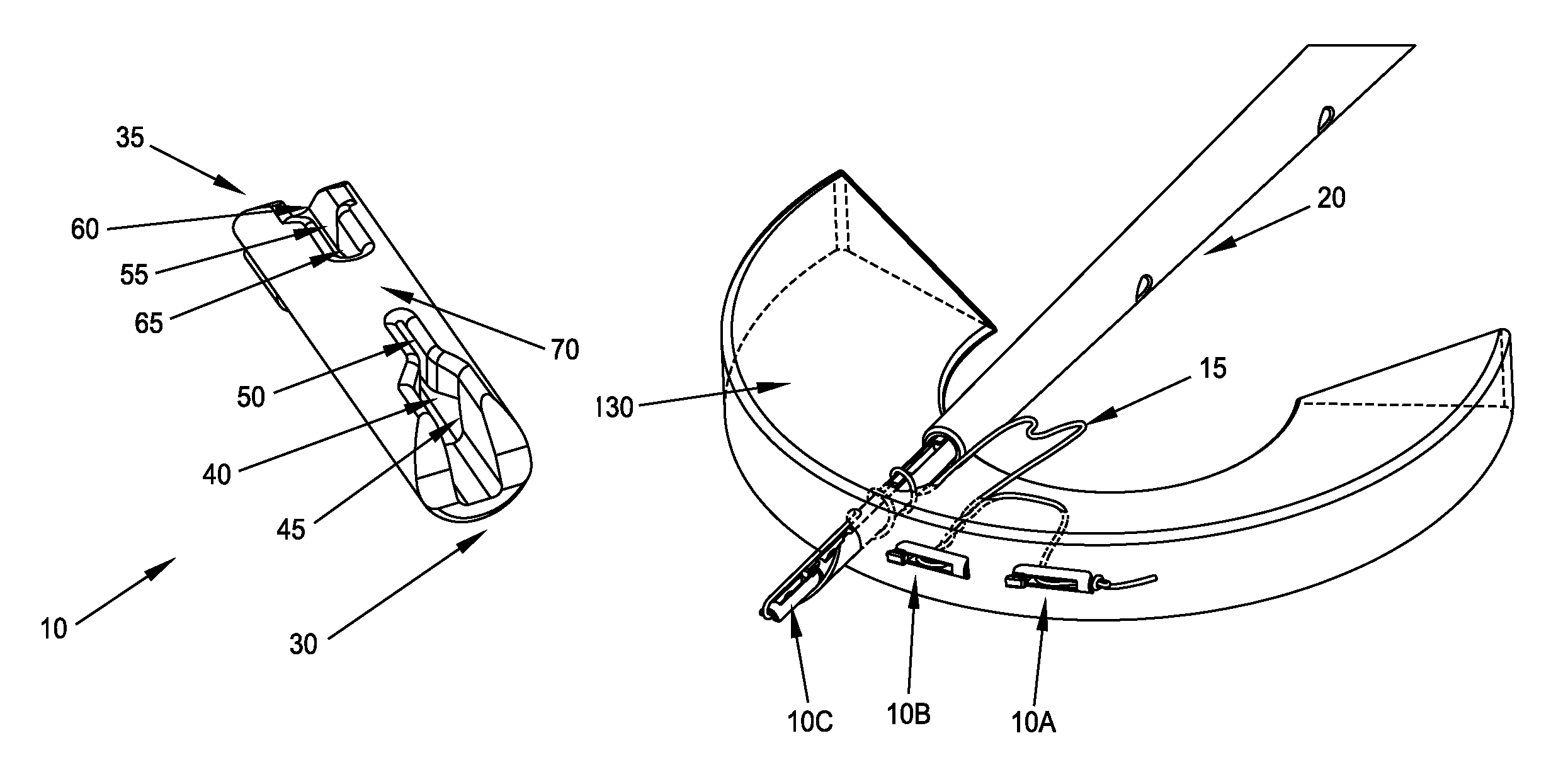
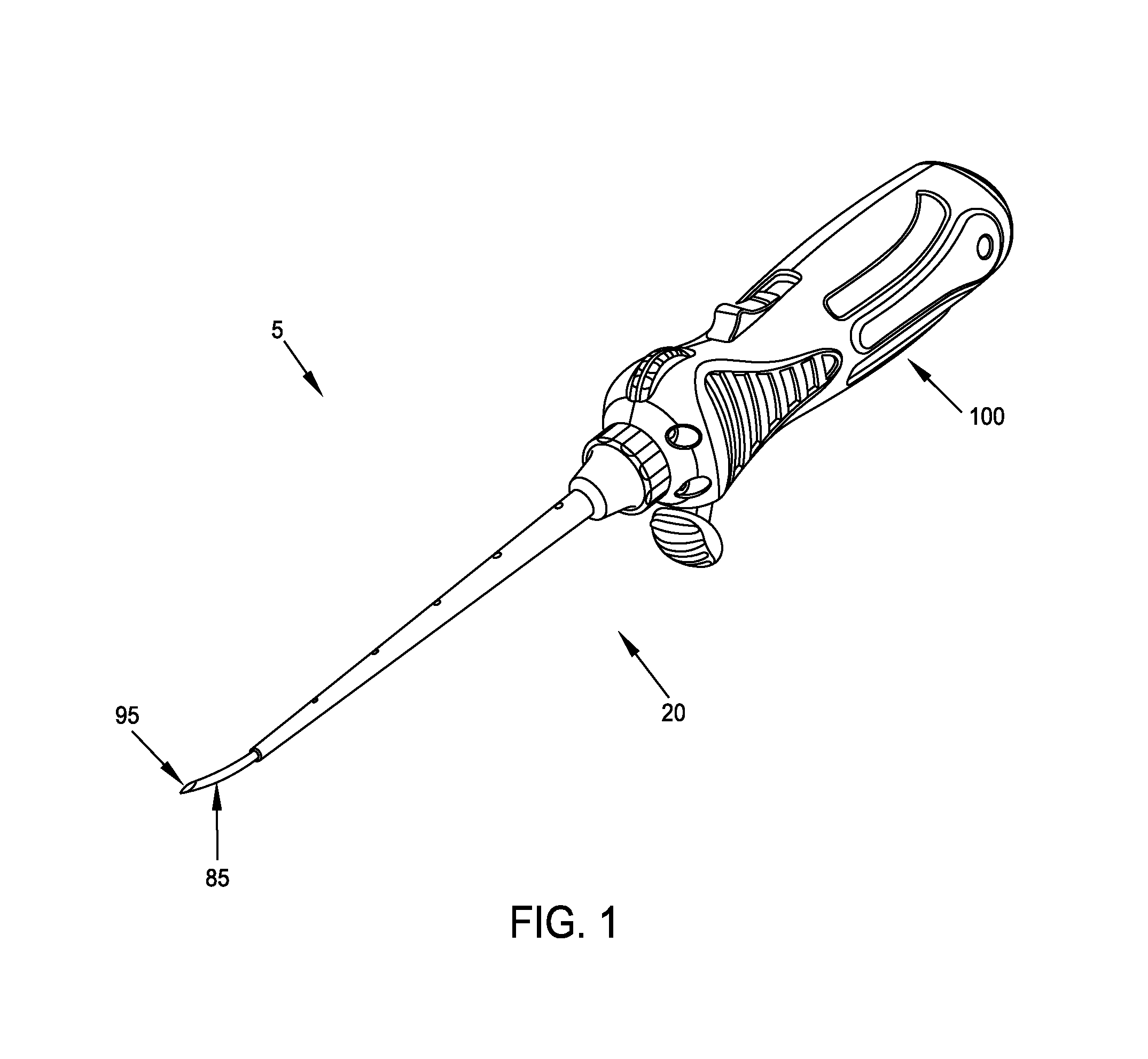
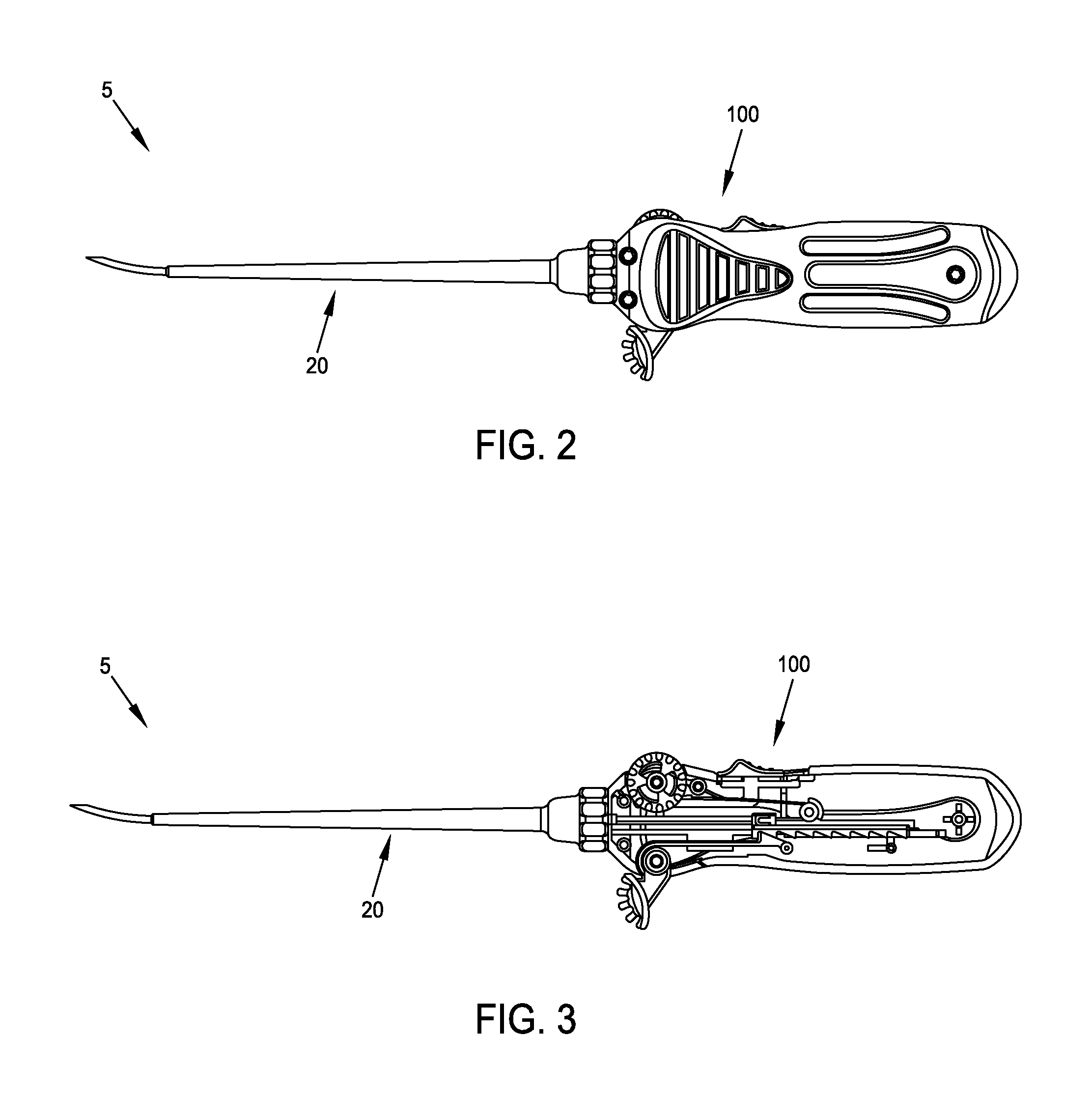
[0089]Looking first at FIGS. 1-6, there is shown a novel system 5 for meniscal repair. System 5 generally comprises a plurality of cleats 10, a length of suture 15 and an inserter 20.

[0090]Cleats 10 are shown in greater detail in FIGS. 7-10, 10A, 10B, 10C, 10D, 10E and 10F. Each of the cleats 10 generally comprises an elongated body 25 which, in its preferred construction, is generally cylindrical so that it can make a close sliding fit within the lumen of a hollow delivery needle, as will hereinafter be discussed in further detail. Elongated body 25 is characterized by a distal end 30 and a proximal end 35.

[0091]On a “bottom” side of elongated body 25, a distal slot 40 extends proximally along the elongated body, with distal slot 40 comprising a wide section 45 and a narrow section 50. Also on the “bottom” side of elongated body 25, a proximal slot 55 extends distally along the elongated body, with proximal slot 55 comprising a wide section 60 and a narrow section 65. Distal slot 4...


PUM


Abstract

A method for securing a first object to a second object, the method comprising providing a suture and a plurality of cleats slidably mounted on the suture; passing one end of the suture and a first cleat through the first object and the second object; tensioning the suture so as to secure the suture to the first cleat; passing a subsequent portion of the suture and a second cleat through the first object and the second object; and tensioning the suture so as to secure the suture to the second cleat.

Description

REFERENCE TO PENDING PRIOR PATENT APPLICATION[0001]This patent application is a continuation-in-part of pending prior U.S. patent application Ser. No. 12 / 417,571, filed Apr. 2, 2009 by David Caborn et al. for METHOD AND APPARATUS FOR MENISCAL REPAIR, which patent application claims benefit of:[0002](i) prior U.S. Provisional Patent Application Ser. No. 61 / 072,683, filed Apr. 2, 2008 by David Caborn et al. for MENISCAL REPAIR MAGAZINE CONCEPT;[0003](ii) prior U.S. Provisional Patent Application Ser. No. 61 / 135,149, filed Jul. 17, 2008 by David Caborn et al. for MENISCAL REPAIR PROVISIONAL 3; and[0004](iii) prior U.S. Provisional Patent Application Ser. No. 61 / 208,294, filed Feb. 23, 2009 by Vincent Novak et al. for MENISCAL REPAIR PROVISIONAL 4.[0005]The four (4) above-identified patent applications are hereby incorporated herein by reference.FIELD OF THE INVENTION[0006]This invention relates to surgical methods and apparatus in general, and more particularly to surgical methods and ...

Claims


Application Information

Patent Timeline
Patent Type & Authority Patents(United States)
IPC IPC(8): A61B17/04
CPCA61B17/0401A61B2017/0409A61B2017/0496A61B2017/0456A61B2017/0417A61B17/0466A61B17/0483A61B2017/00743A61B2017/0414A61B2017/0464
Inventor CABORN, DAVIDMCDEVITT, DENNISNAWAB, AKBARNOVAK, VINCENT
Owner LINVATEC
Why Eureka
Try Eureka