Pedicle screw constructs for spine fixation systems

a technology of spine fixation system and pedicle screw, which is applied in the field of pedicle screw constructs for spine fixation system, orthopedics and/or neurosurgery, can solve the problems of limiting the range of normal spinal motion, threatening the integrity of elements, and causing considerable difficulty

Active Publication Date: 2005-08-25
LIFE SPINE INC
View PDF90 Cites 499 Cited by
  • Summary
  • Abstract
  • Description
  • Claims
  • Application Information

AI Technical Summary

Benefits of technology

[0014] The present invention provides various embodiments of a pedicle screw construct and / or a coupling construct for a pedicle screw for coupling a spinal rod relative to the pedicle screw. The pedicle screw construct may be part of a spine fixation system consisting of one or more connecting rods and one or more pedicle screw constructs. Adjunctive components, not forming a part of the subject invention, may be added such as cross members (that link parallel systems together), hooks and / or the like.

Problems solved by technology

Genetic or irregularities such as developmental irregularities, trauma, tumors, disease and the like, however, can result in spinal pathologies that either limit the range of normal spinal motion or that threatens the integrity of elements of the nervous, circulatory and / or other systems of the spine.
Considerable difficulty, however, was encountered with inserting fixed screws along a misaligned curvature and then simultaneously exactly positioning the coupling devices such that the spinal rod receiving portions of the coupling devices were aligned such that the spinal rod could be passed therethrough without distorting the screws.
However, while the prior art is replete with polyaxial screw and coupling devices for spine fixation systems, they only permit a limited freedom of movement with respect to angulation of the screw and the coupling device.
Moreover, these prior art polyaxial screw and coupling devices are generally complex, inadequately reliable, and lack long-term durability.
Furthermore, these prior art polyaxial screw and coupling devices do not allow the independent fixation of screw to coupling device angulation and rod fixation.
These considerable drawbacks associated with prior art systems also include difficulty properly positioning the rod and coupling devices, and the tedious manipulation of the many small parts in the operation environment.

Method used


Image

  • Pedicle screw constructs for spine fixation systems
  • Pedicle screw constructs for spine fixation systems
  • Pedicle screw constructs for spine fixation systems

Examples


Embodiment Construction

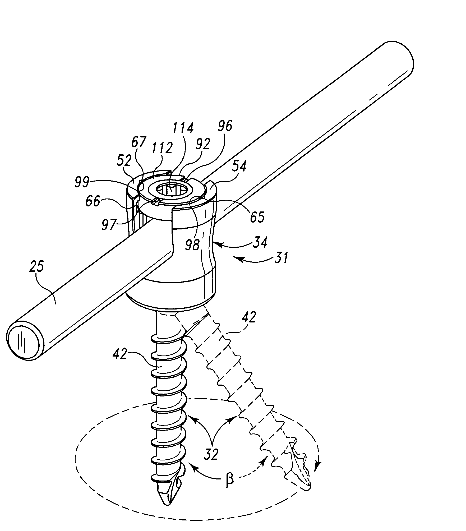
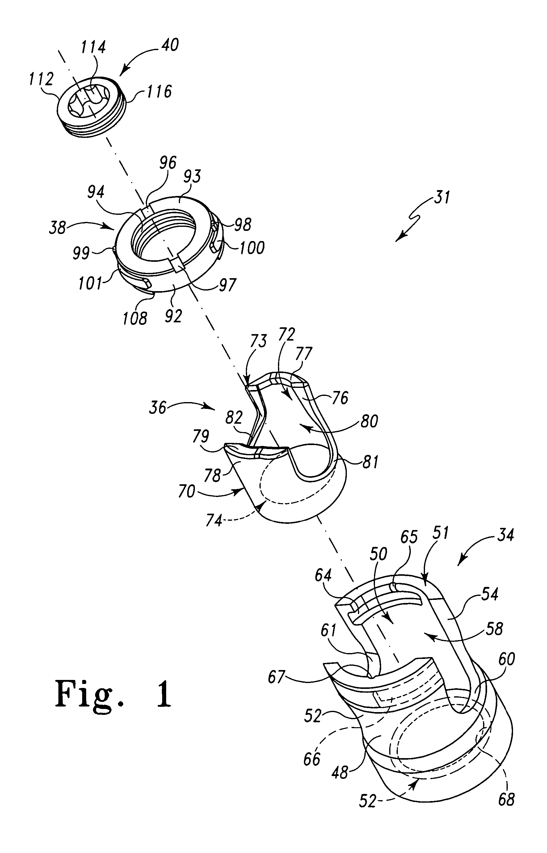
[0046] Referring to FIG. 1, there is depicted an exploded view of an embodiment of a spinal rod fixation device, construct or assembly, generally designated 30. The spinal rod fixation device 30 is used as a component in a spinal rod type spine fixation system or assembly. Particularly, the spinal rod fixation device 30, consisting of a coupling device, construct or assembly 31 and a pedicle screw 32, is used to attach or fix a section of a spinal rod (not shown) of the spine fixation assembly relative to a vertebrae of the spine. More particularly, the pedicle screw 32 is configured, adapted and / or operable to be attached to a vertebra in a known manner, while the coupling construct 31 receives and fixes, retains or holds the section of the spinal rod (the spinal rod is fixed to the coupling construct). The coupling construct 31 is movably positionable relative to the pedicle screw 32 as further described herein. The coupling construct 31 may also be termed a pedicle screw construc...


PUM


Abstract

A pedicle screw coupling construct for a pedicle screw construct provides fixation of angular orientation thereof relative to a pedicle screw independent of fixation of a received spinal rod to the coupling construct. The pedicle screw construct forms one component or element in a spinal fixation system. The independent fixation coupling construct also provides for fixation of the angular orientation of the coupling construct while the coupling construct has received the spinal rod. In another form, a coupling head or construct is configured to allow a pedicle screw shaft to pass therethrough but retain the pedicle screw head for rotation of the coupling head about the pedicle screw head. The coupling head or construct is also configured to allow at least a 45° arc of pivot or articulation about a pedicle screw shaft relative to a longitudinal axis of a spinal rod received in the body. This allows the head with a received spinal rod to fold, bend or pivot relative to the pedicle screw shaft, particularly to a greater degree than the prior art.

Description

[0001] This U.S. non-provisional patent application claims the benefit of and / or priority to U.S. provisional patent application Ser. No. 60 / 536,319 filed Jan. 13, 2004 entitled “Pedicle Screw Construct for a Spine Fixation System”, the entire contents of which is specifically incorporated herein by reference.BACKGROUND OF THE INVENTION [0002] The present invention relates generally to spinal fixation devices for the internal fixation of the spine particularly within the fields of orthopedics and / or neurosurgery such as spinal implants and rods for holding vertebral bones fixed relative to one another and, more particularly, to a polyaxial pedicle screw and / or coupling apparatus for use in spinal surgical procedures for receiving a rod for stabilizing the relative motion of vertebrae. [0003] The spinal column of bones is a highly complex structure that not only allows a high degree of flexible movement in various directions, but also envelopes and protects numerous veins, arteries a...

Claims


Application Information

Patent Timeline
Patent Type & Authority Applications(United States)
IPC IPC(8): A61B17/56A61B17/58A61B17/70
CPCA61B17/7032A61B17/7038A61B17/7037A61B17/7034
Inventor BUTLER, MICHAEL S.YOUSSEF, JIM A.HILIBRAND, ALAN S.
Owner LIFE SPINE INC
Why Eureka
Try Eureka