Expandable support device and method of use

a support device and expandable technology, applied in the field of expandable support devices and methods of use, can solve the problems of excessive pressure, hypertrophy of facet joints, and bending of vertebrae, and achieve the effects of reducing soft tissue trauma, increasing spine height, and providing mechanical support in the spin

Inactive Publication Date: 2008-07-10
STOUT MEDICAL GROUP
View PDF9 Cites 462 Cited by
  • Summary
  • Abstract
  • Description
  • Claims
  • Application Information

AI Technical Summary

Benefits of technology

[0013]A method is disclosed that can include implanting an expandable support device between adjacent bones, such as vertebrae. This less invasive treatment method can increase height in the spine and provide mechanical support in the spine. This method and the associated device can reduce trauma to the soft tissue and reduce the disruption to the ligaments in the spine, increasing spinal stability. The expandable support device can be used as a spinal lift device. The expandable support device can also be used as an expandable space creator, for example between two or more bones, such as vertebra.

Problems solved by technology

This can result in a vertebra “bumping” into an adjacent vertebra, or excessive pressure from one vertebra on the adjacent vertebra.
This “bumping” can result in hypertrophy of the facet joints, or degenerative disc disease, which in turn can force the tissue surrounding the spinal cord and / or dorsal and ventral roots to compress and irritate the respective nerves.
This irritation and compression can cause pain.
Over time this cascading “downward spiral” often gets worse.
This hunching can cause yet more load shifting, and more long-term tissue damage and pain.
However, healthy tissue damage and destruction is required by either of these methods, whether used alone or in combination.
Also, non-target tissue can be damaged, including spinal nerve tissue.
Further this procedure is typically performed in an open surgery, requiring more damage and longer healing time.
However, the prop is not adjustable in height and the straps must be surgically attached around the adjacent vertebra.
The fixed braces are significantly larger than the prop and require an open procedure to deploy, requiring significant additional tissue destruction and damage to deploy than the cam alone.
Further, the cam has a relatively small range of expansion and produces an unnatural, significantly rigid connection between the adjacent vertebrae, much like the static prop.

Method used


Image

  • Expandable support device and method of use
  • Expandable support device and method of use
  • Expandable support device and method of use

Examples


Embodiment Construction

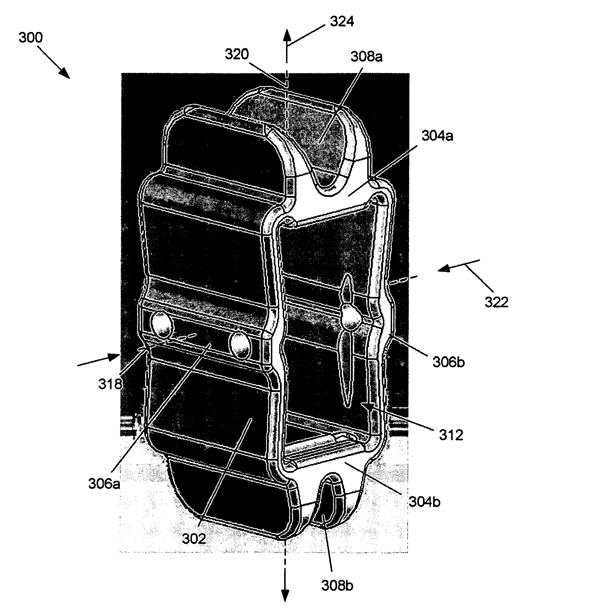
[0064]FIGS. 4a and 4b illustrates that the expandable support device 300 can have an expandable and compressible frame. FIGS. 4a and 4b illustrate the expandable support device in a radially contracted (i.e., flattened, height contracted) configuration.

[0065]The expandable support device 300 can have two, three, four or more struts The struts 302 can be rotationally connected to (i.e., attached to or integrated with) some or all of the other struts 302. The expandable support device 300 can have a top plate 304 and / or a bottom plate 306. The plates 304 can be rotationally connected to one, some or all of the struts 302. The expandable support device 300 can have a first end plate 306a and / or a second end plate 306b. The struts 302 and / or plates 304 and / or 306 can rotationally connect to any or all of each other.

[0066]The struts 30′ and / or plates 304 can have a first vertebral seat 308a and / or a second vertebral seat 308b. The first and second vertebral seats 308a and 308b can be con...


PUM


Abstract

A device for separating a first bone from a second bone is disclosed. The device can be an expandable orthopedic jack. The device can be used to treat spinal stenosis. The device can be deployed between adjacent spinous processes and then increased in height to reduce pressure on nearby nerves. Methods for using the device are also disclosed.

Description

CROSS-REFERENCE TO RELATED APPLICATION[0001]This application claims the benefit of U.S. Provisional Application No. 60 / 878,328, filed 31 Dec. 2006, which is incorporated herein in its entirety.BACKGROUND OF THE INVENTION[0002]1. Field of the Invention[0003]This invention relates to devices for providing support for biological tissue, for example to repair spinal stenosis and / or spinal compression fractures, and methods of using the same.[0004]2. Description of the Related Art[0005]Spinal stenosis is often caused by a shift in the vertebral bodies, which in turn change the static and dynamic nature of the spine. As the spine column shifts, load distributions change, tendons in the spine often shrink, and muscles reorganize and compensate. This can result in a vertebra “bumping” into an adjacent vertebra, or excessive pressure from one vertebra on the adjacent vertebra. This “bumping” can result in hypertrophy of the facet joints, or degenerative disc disease, which in turn can force ...

Claims


Application Information

Patent Timeline
Patent Type & Authority Applications(United States)
IPC IPC(8): A61B17/58A61F2/44A61M29/00
CPCA61B2017/0256A61B17/7065
Inventor GREENHALGH, E. SKOTT
Owner STOUT MEDICAL GROUP
Why Eureka
Try Eureka