Locking subgrade vault

a subgrade vault and locking technology, applied in the field of vaults, can solve the problems of increasing theft, improper security or physical damage of the subgrade system, and presenting hazardous conditions to passersbys and professionals alike, so as to prevent or reduce the risk of chipping and cracking, improve the aesthetics and safety characteristics of the lid

Active Publication Date: 2014-09-16
OLDCASTLE PRECAST
View PDF80 Cites 21 Cited by
  • Summary
  • Abstract
  • Description
  • Claims
  • Application Information

AI Technical Summary

Benefits of technology

[0007]It is one object of the present invention to provide for an improved subgrade or above grade vault system having locking or selectively securing features to prevent unwanted access to an enclosed region. It is another object of the present invention to provide a concrete enclosure adapted for containing subgrade systems wherein the concrete enclosure comprises a lid which can be secured when the lid is generally in a closed or sealed position, thus preventing unwanted or unauthorized access to contents of the enclosure.
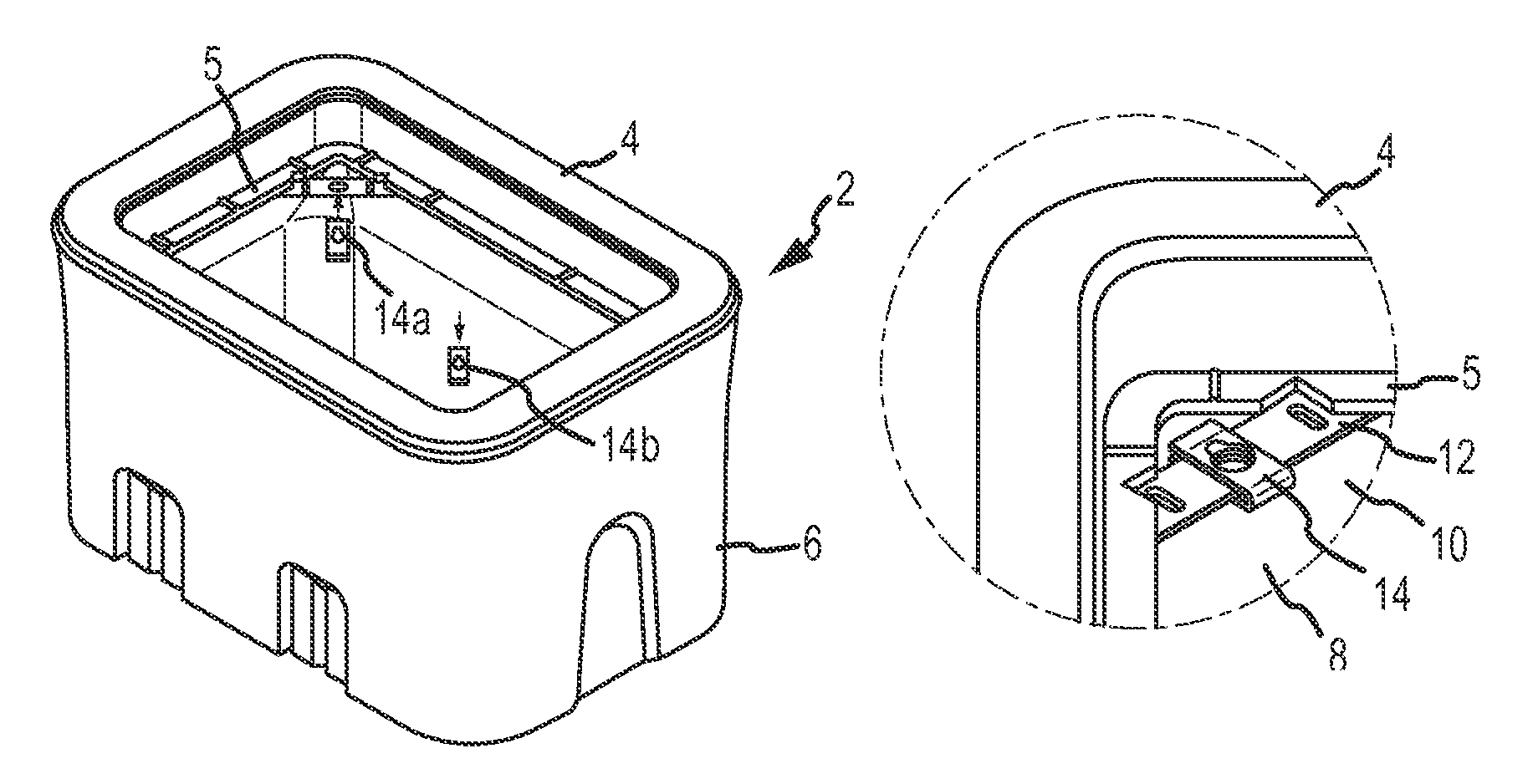
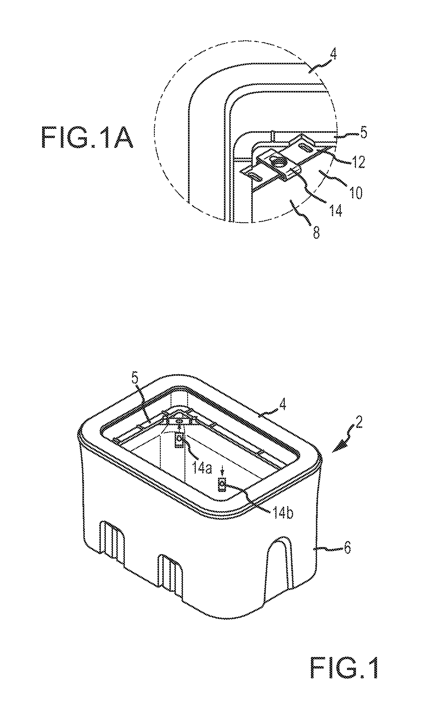
[0013]In various embodiments, a locking member comprises one or more apertures for receiving and securely attaching the locking member to additional components. For example, in one embodiment, a locking member comprises at least one aperture which receives a quantity of concrete and allows concrete to harden or cure in, around, and / or through the locking member. Thus, in various embodiments, a rigid connection between a quantity of concrete and a locking member is obtained, the connection generally being stronger than simply layering or sandwiching a locking member between two regions of concrete. Similarly, apertures may be provided on a locking member for receiving one or more portions of a cap member. For example, a cap member may be provided with pre-formed spikes or extensions which may be placed through portions of a locking member, thus preventing various movements of the locking member with respect to the cap and enhancing the connection between components.
[0015]In one embodiment, a locking member of the present invention comprises a threaded through-hole for receiving a fastener. Obviously, locking features such as threaded through-holes should preferably be disposed in a portion of the locking member that is to be positioned within an open center (i.e. user accessible) portion of the vault. In an alternative embodiment, the present invention comprises a rigid member having a through-hole, the rigid member adapted for receiving a clip or additional component having one or more threaded through-holes. Accordingly, in one embodiment, a locking member is constructed of a minimal amount of material wherein an additional threaded component is adapted to be placed on the locking member, the threaded component comprising the appropriate thickness for a female threaded portion and thereby reducing the need for raw materials and associated cost of the device. In various embodiments, a threaded female portion is adjustable along a length of the locking member. For example, in one embodiment, a plurality of apertures are provided along a length of a locking member, each of the apertures capable of receiving a clip nut, or similar device for receiving a fastener.
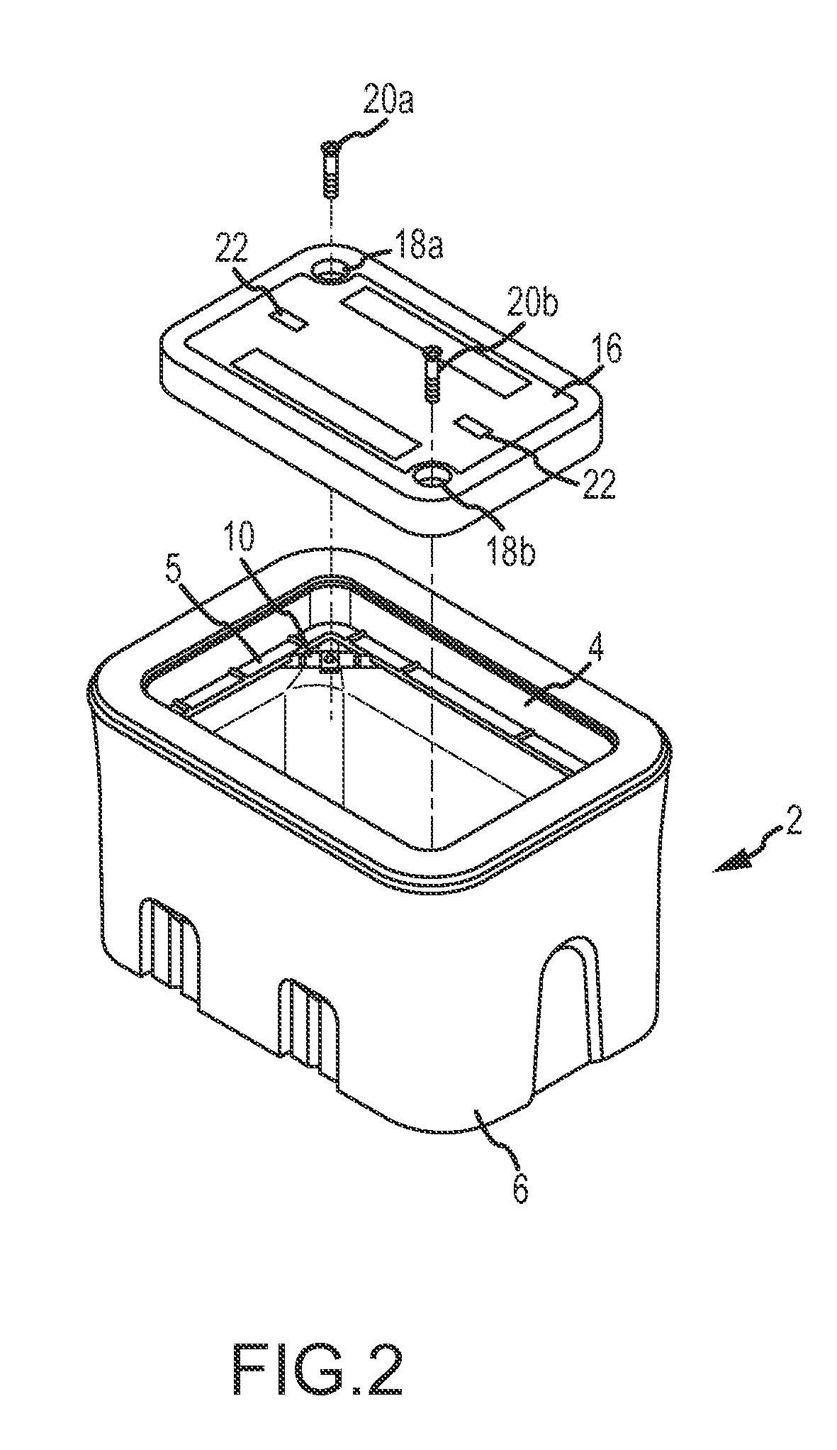
[0019]In various embodiments, the present invention comprises a lid adapted to be secured to a cap. In one embodiment, a lid of the present invention comprises a combination of plastic and a concrete material, wherein an outer portion of the lid is generally comprised of plastic to accommodate stress concentrations at specific locations and generally prevent or reduce the risk of chipping and cracking at corner and perimeter regions of the lid. An inner or central portion is generally comprised of a concrete material, such as Portland cement or precast concrete adapted for accommodating anticipated static and dynamic loading known to be experienced by a subgrade vault with a lid.
[0020]In one embodiment, a lid of the present invention comprises at least one aperture or through-hole and an optional cap, lid, or cover, for selectively sealing the same. The aperture or through-hole is formed such that a locking member is accessible by a fastening member, for example, through the aperture at least when the lid is placed on the cap in a closed position. Accordingly, when a lid is placed on or within a cap of the present invention, an enclosed vault region is established, with access to a locking member(s) provided through an aperture formed in the lid. Thus, when a lid is placed upon a subgrade vault, the lid may be further secured and / or locked to additional components via one or more fasteners. For example, in one embodiment, once a lid is placed upon a cap, one or more apertures formed in the cap provide above-grade access for a threaded fastener such as a bolt to be secured to a female threaded portion secured to a cap / main body portion as previously described. In various embodiments, cap or cover features are provided to cover or conceal apertures and locking hardware formed in a lid, thus providing a generally flush lid surface for improving aesthetic and safety characteristics of the lid.

Problems solved by technology

In part due to the high commodity prices of metals and other internal components, theft is an increasing problem which is not only expensive but extremely disruptive when communication, electrical or water service is discontinued.
Furthermore, improperly secured or physically damaged subgrade systems may present hazardous conditions to passer-bys and professionals alike.
Currently known systems fail to provide adequate safety and security measures for preventing and / or deterring unauthorized access to subgrade storage areas.

Method used


Image

  • Locking subgrade vault
  • Locking subgrade vault
  • Locking subgrade vault

Examples


Embodiment Construction

[0059]The present invention provides its benefits across a broad spectrum of endeavors. It is applicant's intent that this specification and the claims appended hereto be accorded a breadth in keeping with the scope and spirit of the invention being disclosed despite what might appear to be limiting language imposed by the requirements of referring to the specific examples disclosed. To acquaint persons skilled in the pertinent arts most closely related to the present invention, a preferred embodiment of the method that illustrates the best mode now contemplated for putting the invention into practice is described herein by, and with reference to, the annexed drawings that form a part of the specification. The exemplary method is described in detail without attempting to describe all of the various forms and modifications in which the invention might be embodied. As such, the embodiments described herein are illustrative, and as will become apparent to those skilled in the arts, can...


PUM

PropertyMeasurementUnit
thicknessaaaaaaaaaa
lengthaaaaaaaaaa
widthaaaaaaaaaa

Abstract

A subgrade vault system and method of forming the same is provided. Specifically, a subgrade vault suitable for housing utility and similar equipment is provided, the vault comprising a main body portion, a cap, and a lid that may be selectively secured to prevent or deter unauthorized access to vault contents.

Description

[0001]The present application claims the benefit of priority of U.S. Provisional Patent Application 61 / 412,252, filed Nov. 10, 2010, the entire disclosure of which is hereby incorporated by reference in its entirety.FIELD OF THE INVENTION[0002]The present disclosure relates generally to vaults for providing an enclosed region beneath a ground surface. More specifically, vaults are provided comprising a locking lid with a cap assembly for securing various electrical, water, communications and other components and systems below grade of ground level.BACKGROUND OF THE INVENTION[0003]Subgrade vaults are widely used to provide internal enclosed regions where connections can be made and housed. Classic examples of such connections are the joinder of electrical cables used in street lighting, in telephone and communication systems, and water valves for residential communities and golf courses. Such vaults are generally placed below grade of ground level with their upper surfaces at grade w...

Claims


Application Information

Patent Timeline
Patent Type & Authority Patents(United States)
IPC IPC(8): H02G3/08H01F27/02H02G9/10
CPCH02G9/10H01F27/02B65D88/76B65D43/02B65D55/02E05B65/0075H05K5/0221
Inventor FREEMAN, ERIC
Owner OLDCASTLE PRECAST
Why Eureka
Try Eureka