Terminals

a technology of connectors and terminals, applied in the direction of coupling device details, coupling device connections, coupling contact members, etc., can solve the problems of low contact pressure per unit area, low wiping effect, and inability to effectively remove foreign matter adhering to the surface of the recess, etc., to achieve low resistance, improve reliability, and high wiping effect

a technology of connectors and terminals, applied in the direction of coupling device details, coupling device connections, coupling contact members, etc., can solve the problems of low contact pressure per unit area, low wiping effect, and inability to effectively remove foreign matter adhering to the surface of the recess, etc., to achieve low resistance, improve reliability, and high wiping effect

US8840406B2Inactive Publication Date: 2014-09-23MOLEX INC

Image

  • Terminals
  • Terminals
  • Terminals

Examples


Embodiment Construction

[0027]While the Present Application may be susceptible to embodiment in different forms, there is shown in the Figures, and will be described herein in detail, specific embodiments, with the understanding that the disclosure is to be considered an exemplification of the principles of the Present Application, and is not intended to limit the Present Application to that as illustrated.

[0028]In the illustrated embodiments, directional representations—i.e., up, down, left, right; front, rear and the like, used for explaining the structure and movement of the various elements of the Present Application, are relative. These representations are appropriate when the elements are in the position shown in the Figures. If the description of the position of the elements changes, however, it is assumed that these representations are to be changed accordingly.

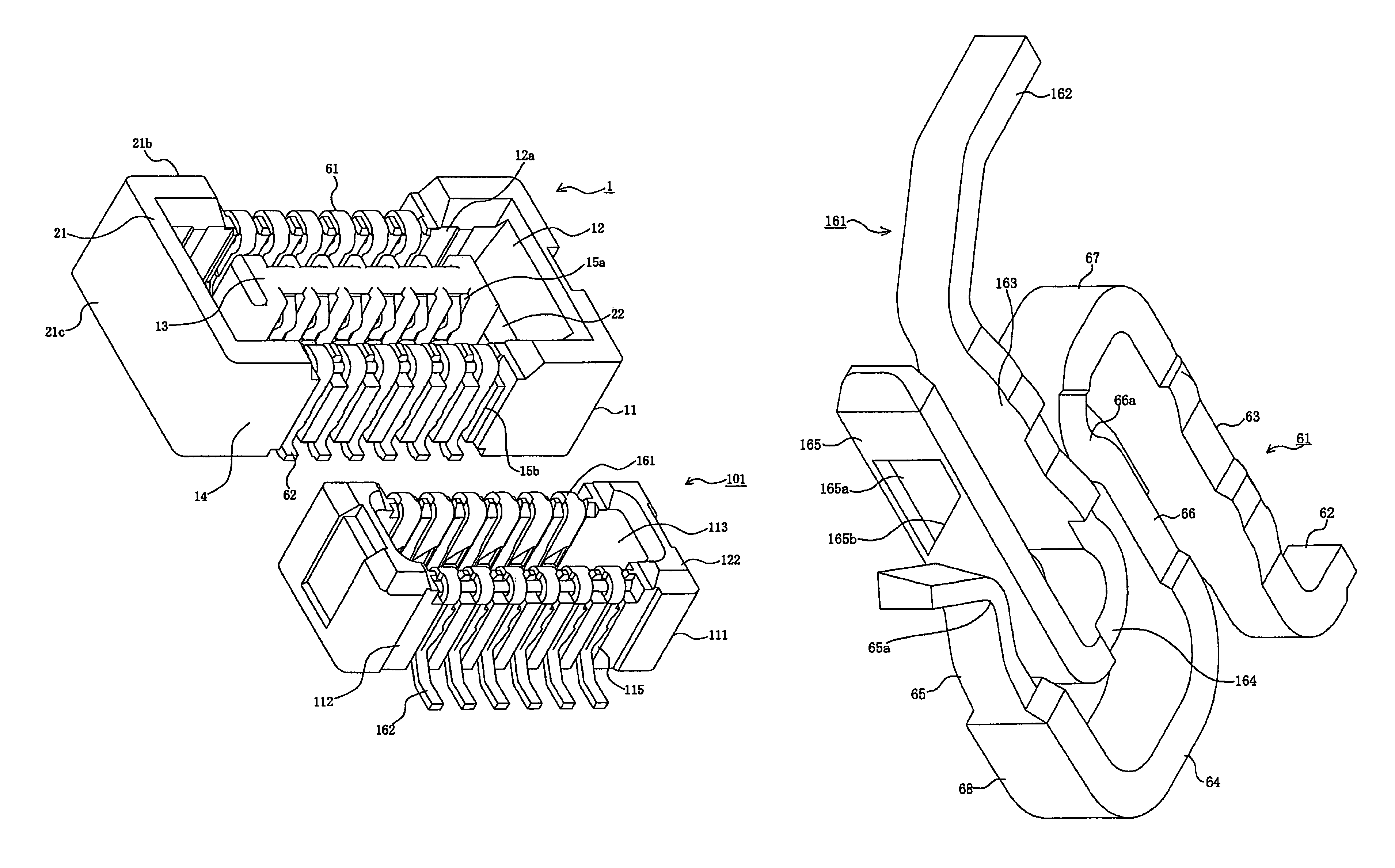
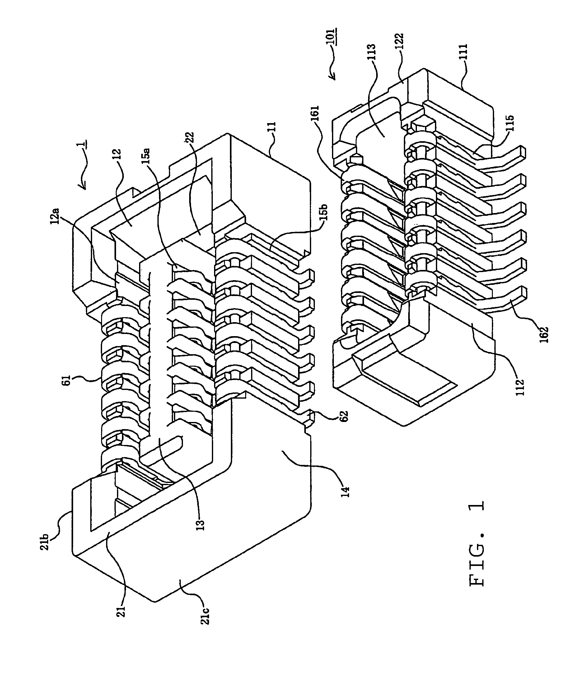
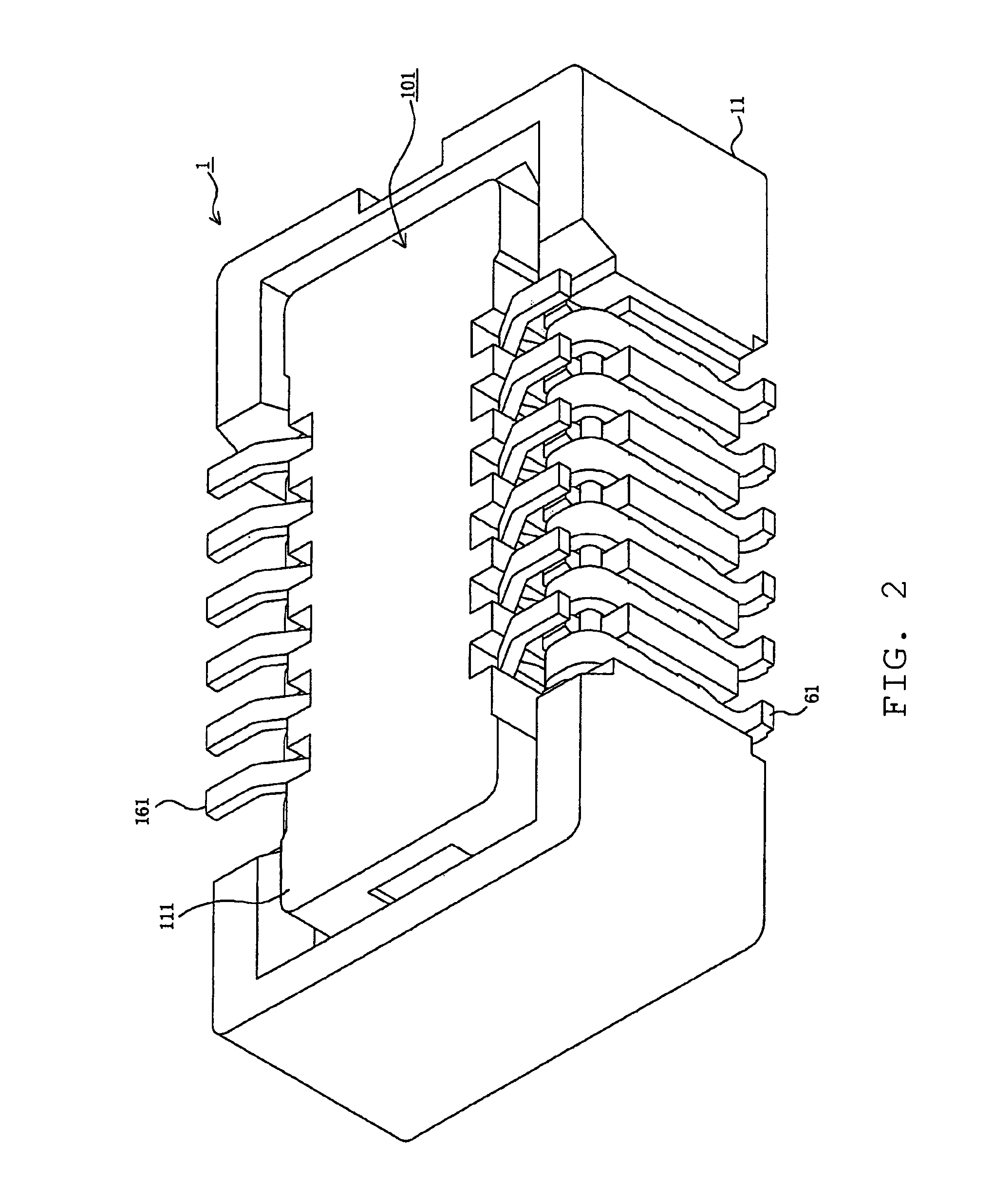
[0029]Referring to FIGS. 1-3, the first connector 1 being one connector in the embodiment of the Present Application, and the second connec...


PUM


Abstract

A pair of terminals having a first terminal loaded in a first connector and a second terminal loaded in a second connector mated with the first connector, the terminals coming into contact with each other and being electrified, wherein the first terminal is equipped with a contact portion including a protruding contact protrusion, the second terminal is equipped with a contact portion including a contact recess engaging the contact protrusion, the contact protrusion is equipped with an oblique portion extending obliquely widthwise relative to the contact portion, the contact recess is equipped with an oblique portion extending obliquely widthwise relative to the contact portion, and the oblique portion of the first terminal and the oblique portion of the second terminal cross each other.

Description

REFERENCE TO RELATED APPLICATIONS[0001]The Present Application claims priority to prior-filed Japanese Patent Application No. 2009-278405, entitled “Terminals,” and filed 18 Dec. 2009, the contents of which is fully incorporated in its entirety herein.BACKGROUND OF THE PRESENT APPLICATION[0002]The Present Application relates generally to terminals loaded in connectors, and, more particularly, to terminals loaded in connectors in which the oblique portion of the terminals are moved, while making point contact so that the oblique portions of the terminals cross each other.[0003]Conventional connectors can be used, for example, to connect a plurality of wires together electrically, to connect a wire (or wires) to a circuit board and to connect a plurality of circuit boards together electrically. When conventional connectors, having a plurality of terminals, are mated, the terminals make contact and are electrified. In order to maintain good contact and a good electrical connection betw...

Claims


Application Information

Patent Timeline
23 Sep 2014
Publication
US8840406B2
IPC
H01R12/00; H01R12/71; H01R13/26
CPC
H01R12/716; H01R13/26
Inventors
HIRATA, TOSHIHISA