Surgical tool with a two degree of freedom wrist

a surgical tool and wrist technology, applied in the field of surgical tools with a two degree of freedom wrist, can solve the problems of reducing the effectiveness of surgical tools, alternative tools with shaft driven clamping mechanisms fail to provide rotational movement of an end effector to mimic the natural action of a surgeon's wrist, etc., and achieve the effect of increasing maneuverability

Active Publication Date: 2014-10-07
INTUITIVE SURGICAL OPERATIONS INC
View PDF106 Cites 1185 Cited by
  • Summary
  • Abstract
  • Description
  • Claims
  • Application Information

AI Technical Summary

Benefits of technology

The patent describes surgical tools with a two degree-of-freedom wrist that can mimic the natural action of a surgeon's wrist, providing better maneuverability for the end effector body. The wrist has an elongate shape that allows for the routing of actuation components and the internal passages for guiding control cables. The wrist uses linked tension members to articulate the end effector body, and the sliding interface surfaces between the tension members and the end effector vary positions of the tension members in correlation with the orientation of the end effector to inhibit changes in tension. The mechanisms for transmitting torque through an angle are also provided, allowing for a high level of force application to tissues through a narrow shaft. The simple arrangement of the mechanisms allows for miniaturization and improved reliability, and the rate of rotation of the drive shaft and the driven shaft are substantially equal even when non-parallel.

Problems solved by technology

Unfortunately, it can be challenging to transmit the desired telesurgical end effector forces through known tool wrists, particularly while retaining the response time, precision, flexibility, and reliability in the tool that is desired for telesurgical tasks.
Unfortunately, many known surgical tools, including known linear clamping, cutting, and stapling tools, lack the ability to transmit desired torques (e.g., tissue clamping torque) or forces (e.g., staple firing force) across a compact articulated wrist, which may reduce the effectiveness of the surgical tool.
Alternative tools with a shaft driven clamping mechanism also fail to provide rotational movement of an end effector to mimic the natural action of a surgeon's wrist.

Method used


Image

  • Surgical tool with a two degree of freedom wrist
  • Surgical tool with a two degree of freedom wrist
  • Surgical tool with a two degree of freedom wrist

Examples


Embodiment Construction

[0095]In the following description, various embodiments of the present invention will be described. For purposes of explanation, specific configurations and details are set forth in order to provide a thorough understanding of the embodiments. However, it will also be apparent to one skilled in the art that the present invention may be practiced without the specific details. Furthermore, well-known features may be omitted or simplified in order not to obscure the embodiment being described.

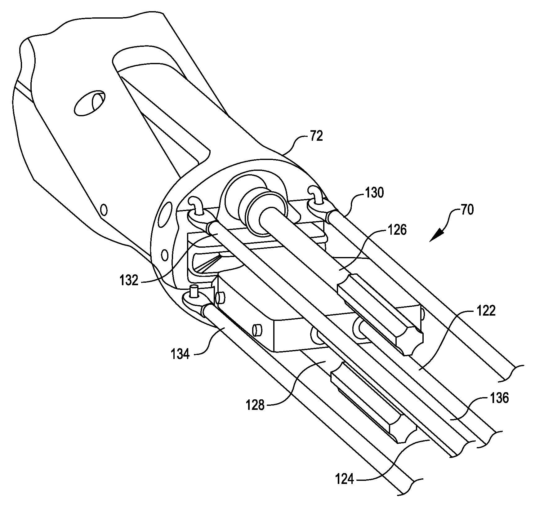
[0096]Surgical tools with a two degree-of-freedom wrist mechanism, and related methods, are provided. In many embodiments, a two degree-of-freedom wrist includes an elongated intermediate wrist member that is pivotally coupled with both a distal end of an instrument shaft and an end effector body. The intermediate member can be pivotally coupled with the instrument shaft to rotate about a first axis that is transverse to an elongate direction of the instrument shaft. The end effector body can be p...


PUM


Abstract

Surgical tools having a two degree-of-freedom wrist, wrist articulation by linked tension members, mechanisms for transmitting torque through an angle, and minimally invasive surgical tools incorporating these features are disclosed. An elongate intermediate wrist member is pivotally coupled with a distal end of an instrument shaft so as to rotate about a first axis transverse to the shaft, and an end effector body is pivotally coupled with the intermediate member so as to rotate about a second axis that is transverse to the first axis. Linked tension members interact with attachment features to articulate the wrist. A torque-transmitting mechanism includes a coupling member, coupling pins, a drive shaft, and a driven shaft. The drive shaft is coupled with the driven shaft so as to control the relative orientations of the drive shaft, the coupling member, and the driven shaft.

Description

CROSS-REFERENCES TO RELATED APPLICATIONS[0001]The present application claims the benefit of U.S. Provisional Application No. 61 / 260,903, entitled “WRIST ARTICULATION BY LINKED TENSION MEMBERS,” filed on Nov. 13, 2009; U.S. Provisional Application No. 61 / 260,910, entitled “DOUBLE UNIVERSAL JOINT,” filed on Nov. 13, 2009; and U.S. Provisional Application No. 61 / 260,915, entitled “SURGICAL TOOL WITH A TWO DEGREE OF FREEDOM WRIST,” filed on Nov. 13, 2009, the full disclosures of which are incorporated herein by reference. The present application is related to U.S. Provisional Application No. 61 / 260,907, entitled “END EFFECTOR WITH REDUNDANT CLOSING MECHANISMS,” filed on Nov. 13, 2009; and U.S. Provisional Application No. 61 / 260,919, entitled “MOTOR INTERFACE FOR PARALLEL DRIVE SHAFTS WITHIN AN INDEPENDENTLY ROTATING MEMBER,” filed on Nov. 13, 2009; the full disclosures of which are incorporated herein by reference.BACKGROUND[0002]Minimally invasive surgical techniques are aimed at reduc...

Claims


Application Information

Patent Timeline
Patent Type & Authority Patents(United States)
IPC IPC(8): A61B17/00A61B19/00F16D3/18F16D3/26
CPCA61B19/2203F16D3/26F16D3/185A61B34/71A61B34/30A61B34/37A61B17/00234A61B17/28A61B17/064A61B17/285A61B2017/00526Y10S901/29A61B2034/305Y10T29/49826A61B34/10
Inventor BURBANK, WILLIAM
Owner INTUITIVE SURGICAL OPERATIONS INC
Why Eureka
Try Eureka