Dereverberation apparatus and dereverberation method

a dereverberation apparatus and dereverberation technology, applied in the direction of electrical transducers, instruments, transmission, etc., can solve the problems of deteriorating dereverberation performance, difficult to presume an initial arrival channel, and inability to say that more channels used provide higher performance, so as to reduce hardware costs, reduce the number of channels, and reduce the time taken for a dereverberation process

Active Publication Date: 2014-10-21
HONDA MOTOR CO LTD
View PDF10 Cites 2 Cited by
  • Summary
  • Abstract
  • Description
  • Claims
  • Application Information

AI Technical Summary

Benefits of technology

[0014]It is another object of the present invention to provide a dereverberation apparatus and a dereverberation method which are capable of dereverberation even when an initial arrival channel is unknown.
[0042]According to the fourteenth aspect of the invention, since a predetermined representative channel can be set to a channel at which the sound signal initially arrives, it is possible to reduce reverberation with high precision even when an initial arrival channel is unknown.

Problems solved by technology

However, since there exist channels with similar impulse responses depending on the arrangement of microphones, it cannot be necessarily said that more channels used provide higher performance.
Specifically, if channels with similar transfer characteristics from a sound source to microphones are included, there may arise a problem of deterioration of dereverberation performance due to poor conditions of a matrix.
In addition, if a sound source may be anywhere such as with a robot hearing sense, it is difficult to presume an initial arrival channel.

Method used


Image

  • Dereverberation apparatus and dereverberation method
  • Dereverberation apparatus and dereverberation method
  • Dereverberation apparatus and dereverberation method

Examples


first embodiment

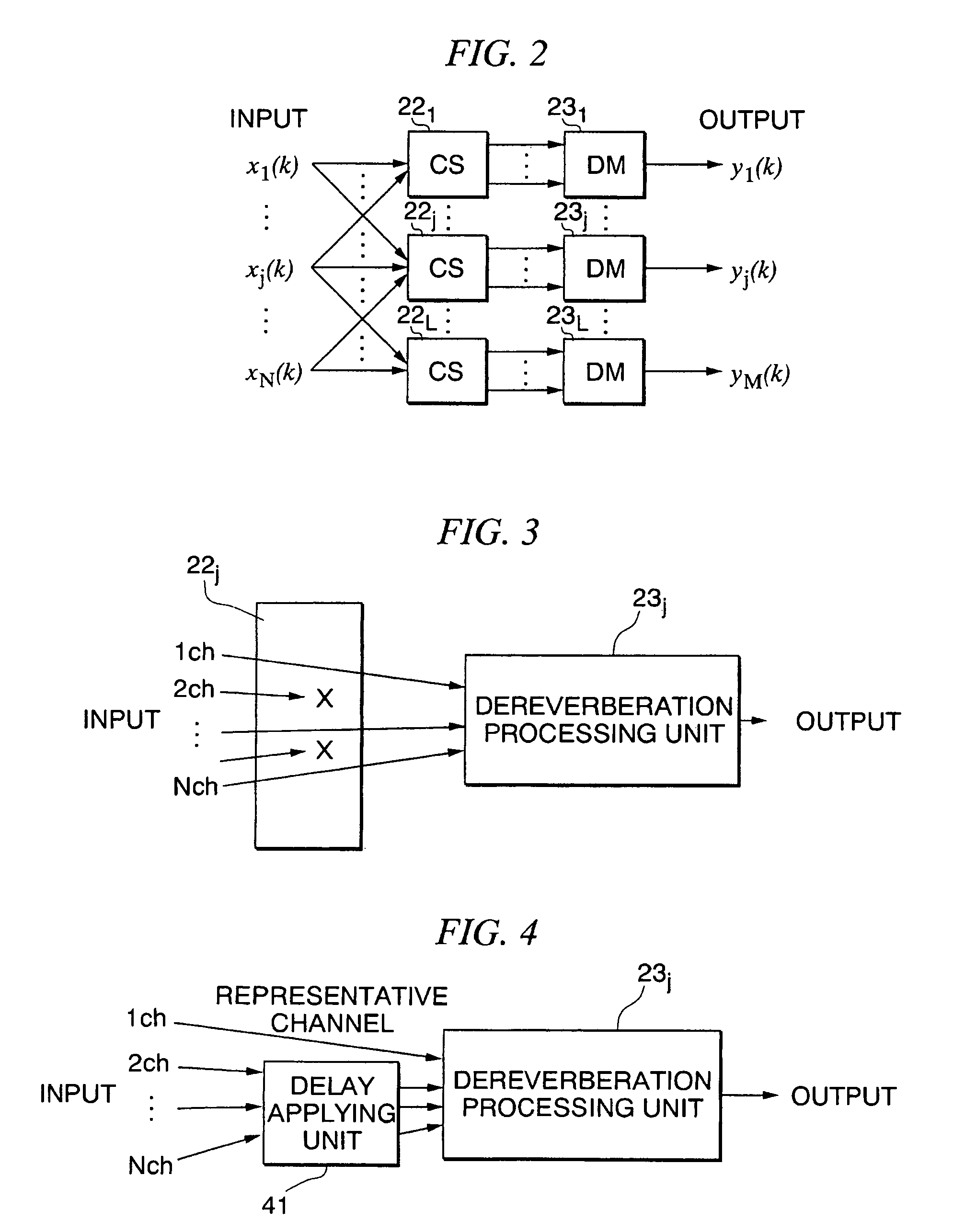
[0063]Hereinafter, embodiments of the present invention will be described in detail with reference to the accompanying drawings. In the related art, a dereverberation process was performed using all available channels since more channels generally provide higher dereverberation performance. However, since there may exist channels with similar acoustic transfer functions (hereinafter referred to as “impulse response”) from a sound source to a microphone depending on arrangement of the microphone, it cannot be necessarily said that more channels provide higher dereverberation performance. Therefore, the present invention performs a process of selecting the channels to be used (channel selection).

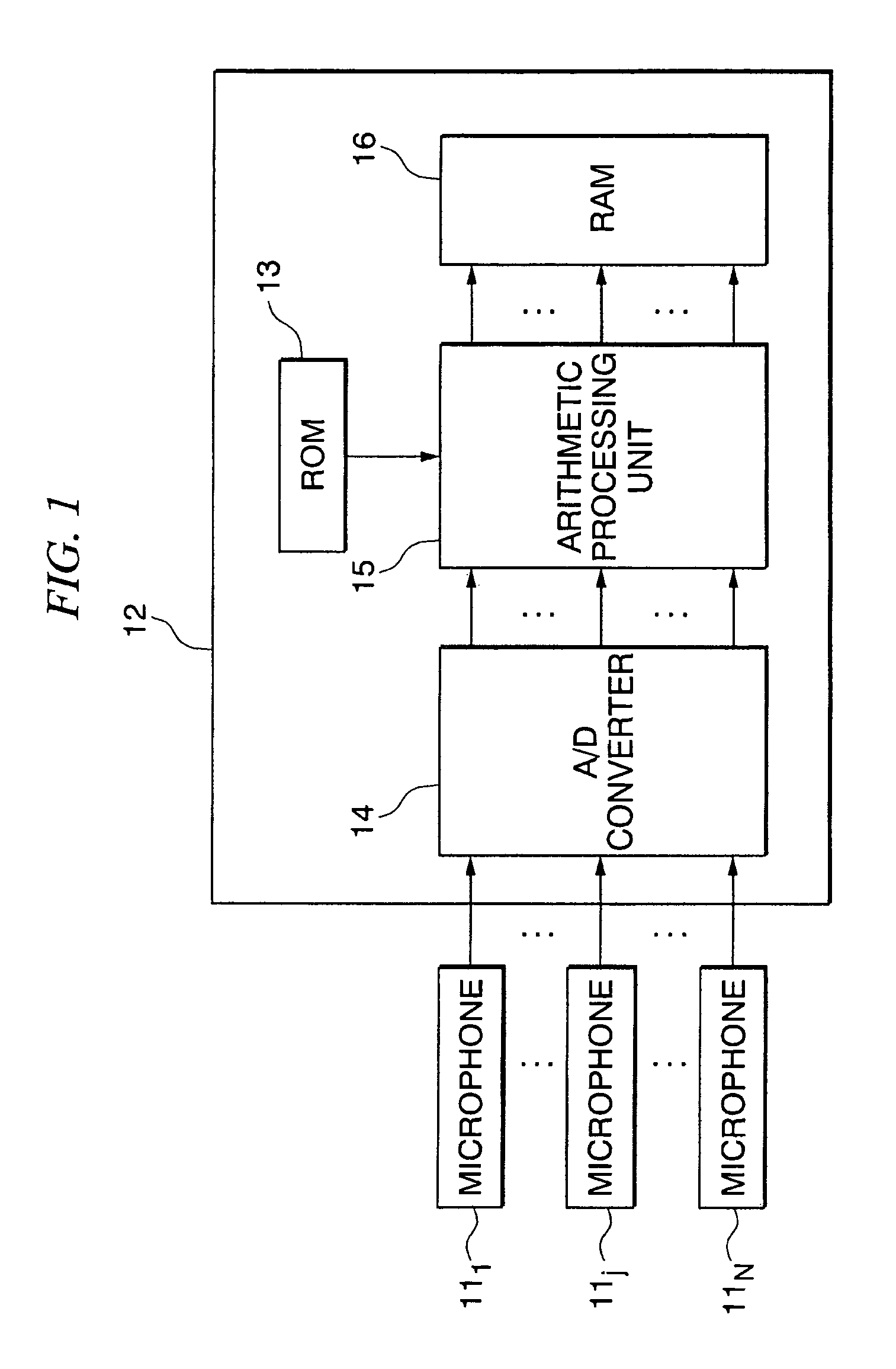
[0064]FIG. 1 is a block diagram of a configuration of a dereverberation apparatus according to an embodiment of the present invention. The dereverberation apparatus includes a microphone 11j (j is an integer between 1 and N) and an electronic control unit 12. The electronic control unit 12 inc...

second embodiment

[0112]Next, a multi-stage dereverberation apparatus according to the present invention will be described. A multi-stage dereverberation process refers to performing a dereverberation process in a recursive manner using a plurality of dereverberation signals obtained by different channel selections. According to this process, it can be expected to obtain high dereverberation performance even in a case where sufficient dereverberation performance cannot be obtained by a single process. FIG. 14 is a block diagram of a configuration of an arithmetic processing unit 15 of the multi-stage dereverberation apparatus. The multi-stage dereverberation apparatus includes M (M is a positive integer) dereverberation units 151, 152, . . . , 15M.

[0113]A first-stage dereverberation unit 151 includes a first-stage channel selecting unit (CS) 16j (j is an integer between 1 and P(1)) and a first-stage dereverberation processing unit (DM) 17j (j is an integer between 1 and P(1)).

[0114]A second-stage der...


PUM


Abstract

A dereverberation apparatus includes a signal selecting unit which selects a sound signal to be used for dereverberation process from a plurality of sound signals, and a dereverberation processing unit which performs the dereverberation process for the selected sound signal.

Description

CROSS REFERENCE TO RELATED APPLICATIONS[0001]This application claims benefit from U.S. Provisional application Ser. No. 61 / 152,355, filed Feb. 13, 2009, the contents of which are incorporated herein by reference.BACKGROUND OF THE INVENTION[0002]1. Field of the Invention[0003]The present invention relates to a dereverberation apparatus and a dereverberation method.[0004]2. Description of the Related Art[0005]A reverberation reducing process is an important technique used to pre-process auto-speech recognition, aiming at improvement of articulation in a teleconference call or a hearing aid and improvement of a recognition rate of auto-speech recognition used for speech recognition of a robot (robot hearing sense) (see, for example, Japanese Unexamined Patent Application, First Publication No. H09-261133). In the related art, there has been proposed a reverberation reducing process based on a Multiple-input / output INverse-filtering Theorem (MINT) which is theoretically capable of derev...

Claims


Application Information

Patent Timeline
Patent Type & Authority Patents(United States)
IPC IPC(8): H04R1/40H04R27/00H04R29/00G10L21/0208
CPCH04R2227/009H04R1/406H04R27/00
Inventor NAKAJIMA, HIROFUMINAKADAI, KAZUHIROHASEGAWA, YUJI
Owner HONDA MOTOR CO LTD
Why Eureka
Try Eureka