Ultrasonic transceiver and ultrasonic flow meter

a transceiver and ultrasonic technology, applied in the direction of electrical transducers, measurement devices, instruments, etc., can solve the problems of erroneous detection of gas flow rate and inability to accurately detect the reference point for propagation time measuremen

Pending Publication Date: 2022-07-21
PANASONIC INTELLECTUAL PROPERTY MANAGEMENT CO LTD
View PDF0 Cites 1 Cited by
  • Summary
  • Abstract
  • Description
  • Claims
  • Application Information

AI Technical Summary

Problems solved by technology

However, in the conventional configuration, since a reverberation in the received wave of the ultrasonic wave is large, there is a pos...

Method used


Image

  • Ultrasonic transceiver and ultrasonic flow meter
  • Ultrasonic transceiver and ultrasonic flow meter
  • Ultrasonic transceiver and ultrasonic flow meter

Examples


first exemplary embodiment

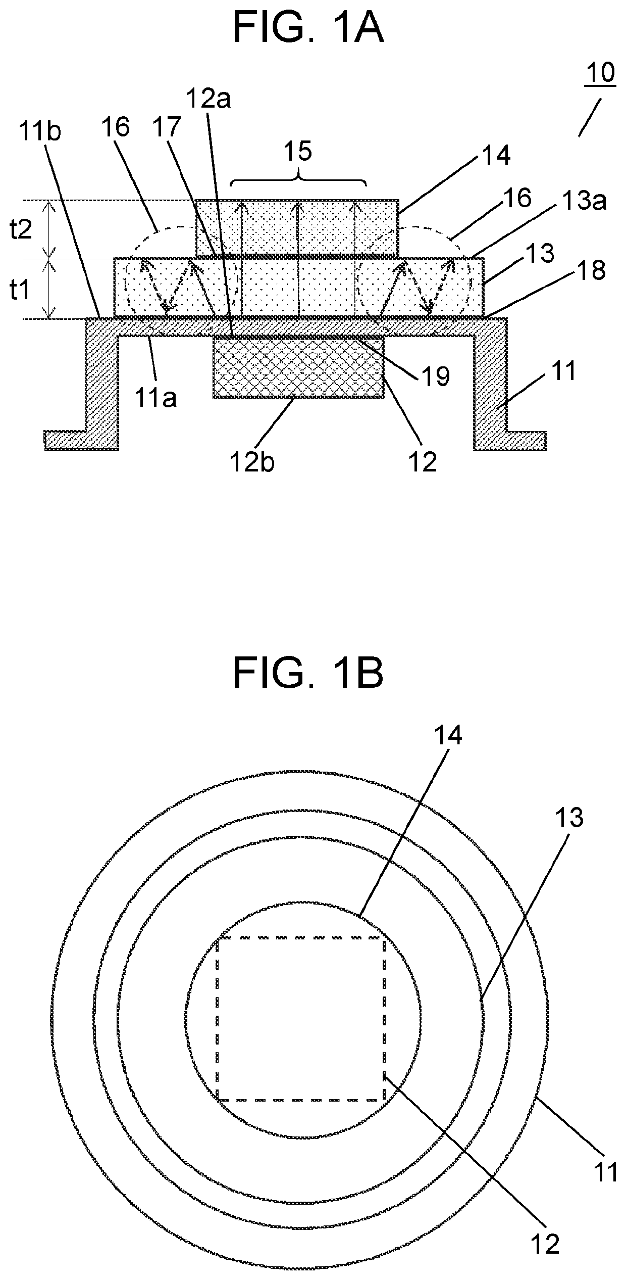
[0053]FIG. 1A is a cross-sectional view of an ultrasonic transceiver in a first exemplary embodiment. FIG. 1B is a plan view of the ultrasonic transceiver in the first exemplary embodiment.

[0054]With reference to FIGS. 1A and 1B, ultrasonic transceiver 10 includes case 11 having conductivity and a capped cylindrical shape, piezoelectric element 12 joined to top face inner part 11a of case 11 via joining part 19, first acoustic matching layer 13 joined to top face outer part lib of case 11 via joining part 18, and second acoustic matching layer 14 joined to first acoustic matching layer 13 via joining part 17.

[0055]Electrodes 12a and 12b are provided on opposite surfaces of piezoelectric element 12, electrode 12a is conductively joined to case 11 via joining part 19, and when an AC voltage is applied across electrode 12b and case 11, piezoelectric element 12 is deformed according to the voltage. The deformation generated in piezoelectric element 12 propagates to a fluid to be measure...

second exemplary embodiment

[0074]Next, an ultrasonic flow meter using the ultrasonic transceiver described in the first exemplary embodiment will be described with reference to FIGS. 5, 6, and 7.

[0075]FIG. 5A is a perspective view of an ultrasonic transceiver used for an ultrasonic flow meter in a second exemplary embodiment. FIG. 5B is a perspective view of the ultrasonic transceiver used for the ultrasonic flow meter in the second exemplary embodiment. FIG. 5C is a plan view of the ultrasonic transceiver used for the ultrasonic flow meter in the second exemplary embodiment. FIG. 5D is a cross-sectional view taken along line 5D-5D of FIG. 5C.

[0076]As illustrated in the drawings, in ultrasonic transceiver 40, electrode surface 42a of piezoelectric element 42 is conductively joined to top part inner side 41a of metal case 41 having a capped cylindrical shape, and lead wire 46 is joined to electrode surface 42b by solder 49. In addition, lead wire 47 is joined to case 41 by welding, and piezoelectric element 42...


PUM


Abstract

There are provided piezoelectric element, case having conductivity, first acoustic matching layer bonded on case, and second acoustic matching layer stacked on and bonded to first acoustic matching layer. A joining part between first acoustic matching layer and second acoustic matching layer is located inside an outer periphery of a joining surface of first acoustic matching layer that is joined to second acoustic matching layer. This configuration can prevent indirect wave generated in first acoustic matching layer from propagating to second acoustic matching layer, and can therefore reduce reverberation of an ultrasonic wave.

Description

TECHNICAL FIELD[0001]The present disclosure relates to an ultrasonic transceiver that transmits and receives an ultrasonic wave by using a piezoelectric element or the like, and an ultrasonic flow meter using the same.BACKGROUND ART[0002]In recent years, an ultrasonic flow meter that measures a time taken for an ultrasonic wave to travel in a propagation path, thereby measuring a moving speed of a fluid, and consequently measures a flow rate has been being used for gas meters and the like. In an ultrasonic flow meter that performs flow rate measurement by measuring a propagation time of an ultrasonic wave, a pair of ultrasonic transceivers are generally disposed upstream and downstream of a measurement flow path through which a fluid to be measured flows, and the propagation time of the ultrasonic wave is measured by transmission and reception of an ultrasonic wave between the ultrasonic transceivers.[0003]When the fluid to be measured is a gas, the difference in acoustic impedance ...

Claims


Application Information

Patent Timeline
IPC IPC(8): G01F1/66G01F1/667H04R17/00
CPCG01F1/662H04R17/00G01F1/668G01F1/667
Inventor ISHIZAKI, YUDAIMASUDA, TOMOKINAGAHARA, HIDETOMO
Owner PANASONIC INTELLECTUAL PROPERTY MANAGEMENT CO LTD
Why Eureka
Try Eureka