
Method and device for rapidly measuring dielectric loss angle based on time domain quasi-synchronization

A time-domain quasi-synchronization and measurement method technology, which can be used in measurement devices, measurement of electrical variables, measurement of resistance/reaction/impedance, etc., and can solve problems such as low efficiency, large amount of data, and large amount of calculation

Inactive Publication Date: 2014-04-30
HUNAN UNIV
View PDF6 Cites 22 Cited by
  • Summary
  • Abstract
  • Description
  • Claims
  • Application Information

AI Technical Summary

Problems solved by technology

[0008] To sum up, the existing technology has the following defects: (1) The methods such as the orthogonal filtering method and the high-order sinusoidal fitting method are complex in algorithm and inefficient, and are not easy to implement in embedded systems; (2) The FFT algorithm is highly efficient However, due to the influence of asynchronous sampling, the FFT algorithm inevitably has spectrum leakage and fence effect; (3) Due to the spectrum leakage and fence effect, the FFT algorithm needs to use window The function and spectral line interpolation algorithm has the disadvantages of large amount of calculation, long sampling data time and large amount of data, and the algorithm is complex

Method used


Image

  • Method and device for rapidly measuring dielectric loss angle based on time domain quasi-synchronization
  • Method and device for rapidly measuring dielectric loss angle based on time domain quasi-synchronization
  • Method and device for rapidly measuring dielectric loss angle based on time domain quasi-synchronization

Examples


Embodiment

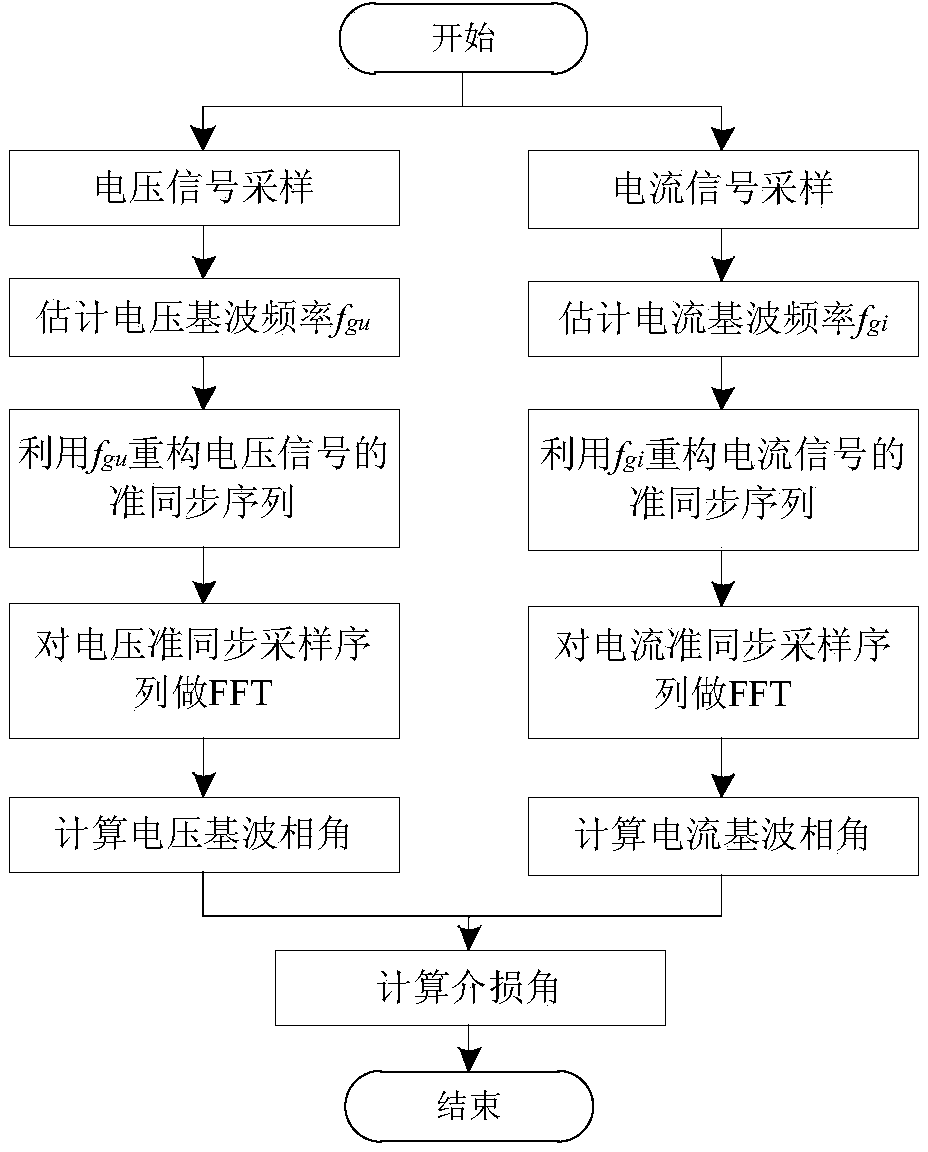
[0052] refer to figure 1 , this embodiment includes the following steps:

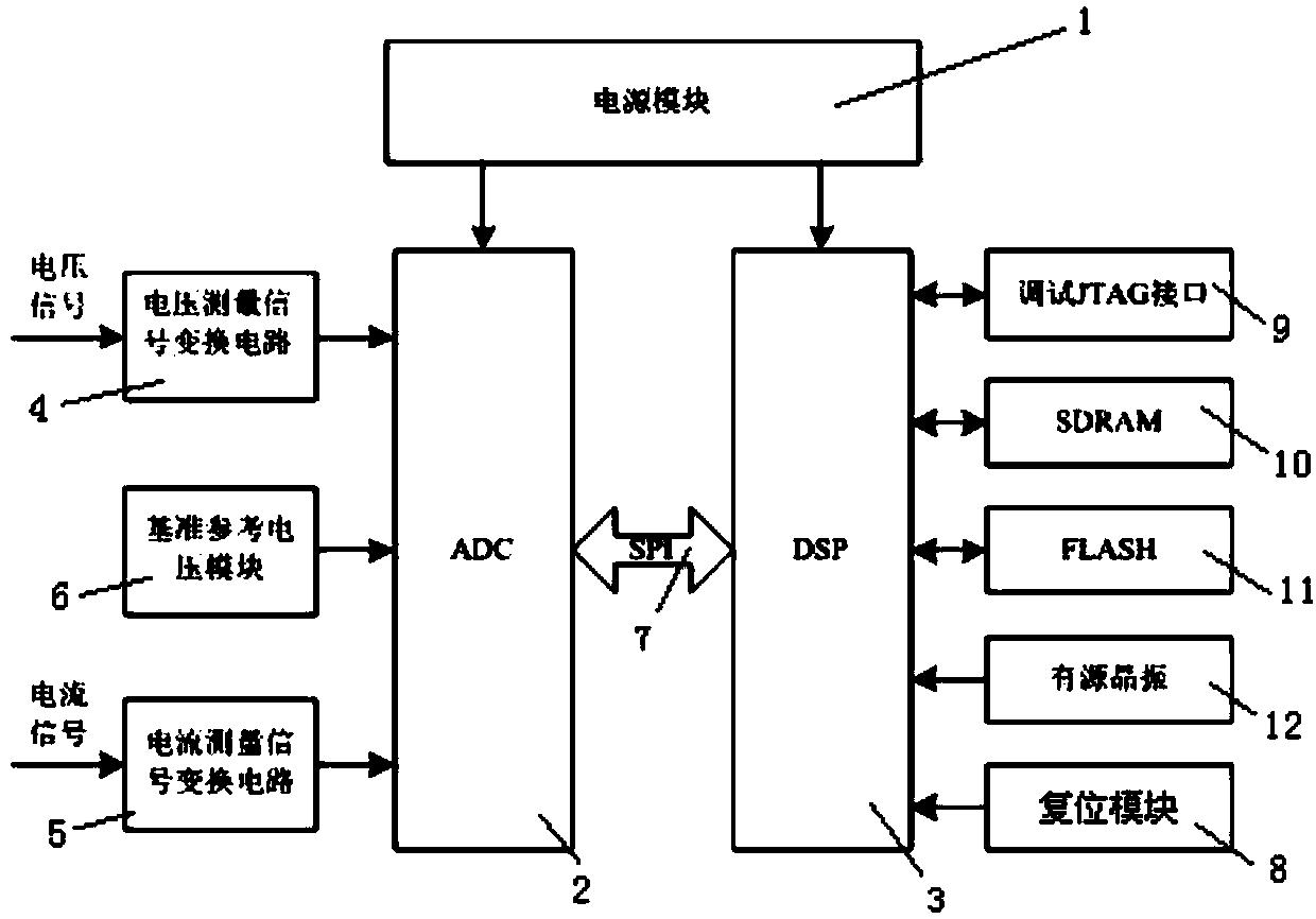
[0053] (1) Signal sampling: the voltage signal and current signal on the capacitive device are transformed into a small-amplitude voltage signal and a small-amplitude current signal that meet the input requirements of the analog-to-digital converter through the voltage measurement signal conversion circuit and the current measurement signal conversion circuit respectively , the analog-to-digital converter converts the small-amplitude voltage signal and small-amplitude current signal into digital quantities, and sends them to the digital signal processor through the SPI bus to obtain voltage sampling signals and current sampling signals;

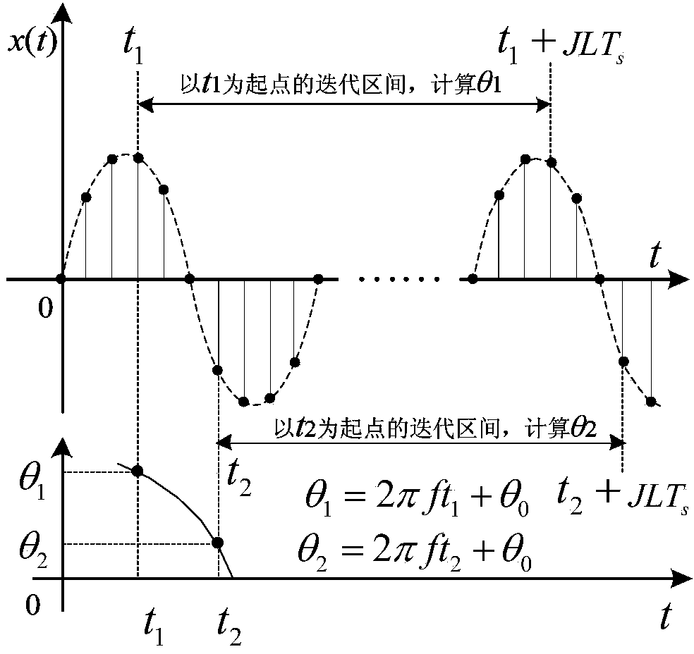
[0054] (2) Estimate the fundamental frequency: the digital signal processor uses the quasi-synchronous sampling algorithm to analyze the signal sampled in step (1), and estimate the fundamental frequency of the voltage sampling signal and the fundamental frequency of t...


PUM


Abstract

The invention discloses a method and device for rapidly measuring a dielectric loss angle based on time domain quasi-synchronization. The measuring method comprises the following steps of signal sampling, fundamental frequency estimation, reconstitution of a quasi-synchronization sampling sequence of sampled signals, frequency analysis based on the FFT, fundamental wave phase angle calculation and dielectric loss angle calculation. The measuring device comprises a power module. The power module is respectively and electrically connected with an analog-digital converter and a digital signal processor. The analog-digital converter is respectively connected with a voltage measurement signal converting circuit, a current measurement signal converting circuit and a standard reference voltage module. The analog-digital converter is connected with a digital signal processor through an SPI. The digital signal processor is electrically and respectively connected with a reset module, a debugging JTAG interface, a synchronization dynamic random access memory, an FLASH and an active crystal oscillator. According to the detecting method, rapid, accurate and stable measurement of the dielectric loss angle can be achieved, sampling time is short, the sampling data size is small, the algorithm is simple, operand is small, and an embedded system is easy to obtain. The measuring device is accurate in measurement.

Description

technical field [0001] The invention relates to a fast measurement method of dielectric loss angle based on time domain quasi-synchronization and a measurement device thereof. Background technique [0002] Dielectric loss angle (dielectric loss angle δ) is an important index to study the insulation aging performance of high-voltage capacitive equipment, and its change can reflect insulation defects such as moisture, deterioration or gas discharge in the insulator. With the development of power system on-line monitoring technology and digital signal processing technology, the high-accuracy dielectric loss angle measurement algorithm has attracted more and more attention. [0003] At present, the dielectric loss angle measurement can be realized by hardware circuit and digital signal processing technology. [0004] The hardware circuit method (such as zero-crossing comparison method and bridge balance method) has high accuracy, but has weak anti-interference ability and high ...

Claims


Application Information

Patent Timeline
IPC IPC(8): G01R27/26
Inventor 王康滕召胜唐求高云鹏温和姚文轩谭霞张海焕左培丽成达吴禹李峰温冠华孟卓
Owner HUNAN UNIV
Learn More