Method and device for camera calibration

a camera and calibration technology, applied in the field of camera calibration, can solve the problems of not always available, difficult manual arrangement of implementing the 3d control scene method, and current camera self-calibration technology is not very reliable,

Active Publication Date: 2014-10-28
VIMICRO CORP
View PDF2 Cites 10 Cited by
  • Summary
  • Abstract
  • Description
  • Claims
  • Application Information

AI Technical Summary

Benefits of technology

[0010]In general, the present invention pertains to methods and devices for calibrating camera parameters. According to one aspect of the present invention, objects on an image are detected and features on the objects, such as the top of a person, are identified. Perspective parallel lines based on the object features are constructed and vanishing points from the converged perspective parallel lines are determined. A vanishing line is defined according to the vanishing points. The intrinsic parameters, such as focal length, and the extrinsic parameters, such as tilting and pan angles, of a camera are calibrated according to the vanishing points, the vanishing line and a reference object with known dimensions, or known camera angles, The calibrated camera parameters are used for accurate photogrammetric measurements and computer vision applications.

Problems solved by technology

However, implementing the 3D control scene method is a complex and difficult manual arrangement, and it is not always available for every applications.
However, the current technology in the camera self-calibration is not very reliable and has lower calibration accuracy.

Method used


Image

  • Method and device for camera calibration
  • Method and device for camera calibration
  • Method and device for camera calibration

Examples


first embodiment

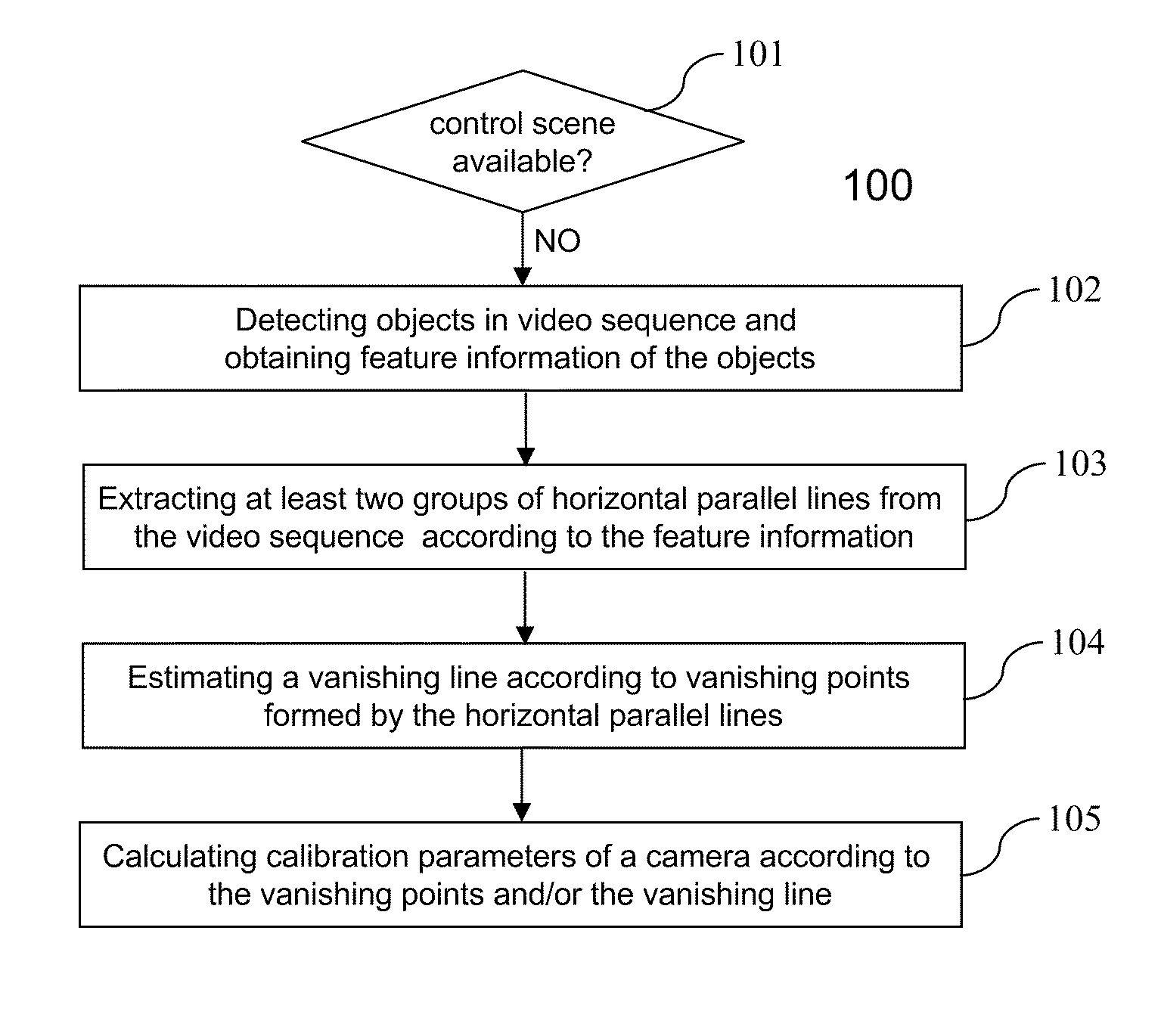
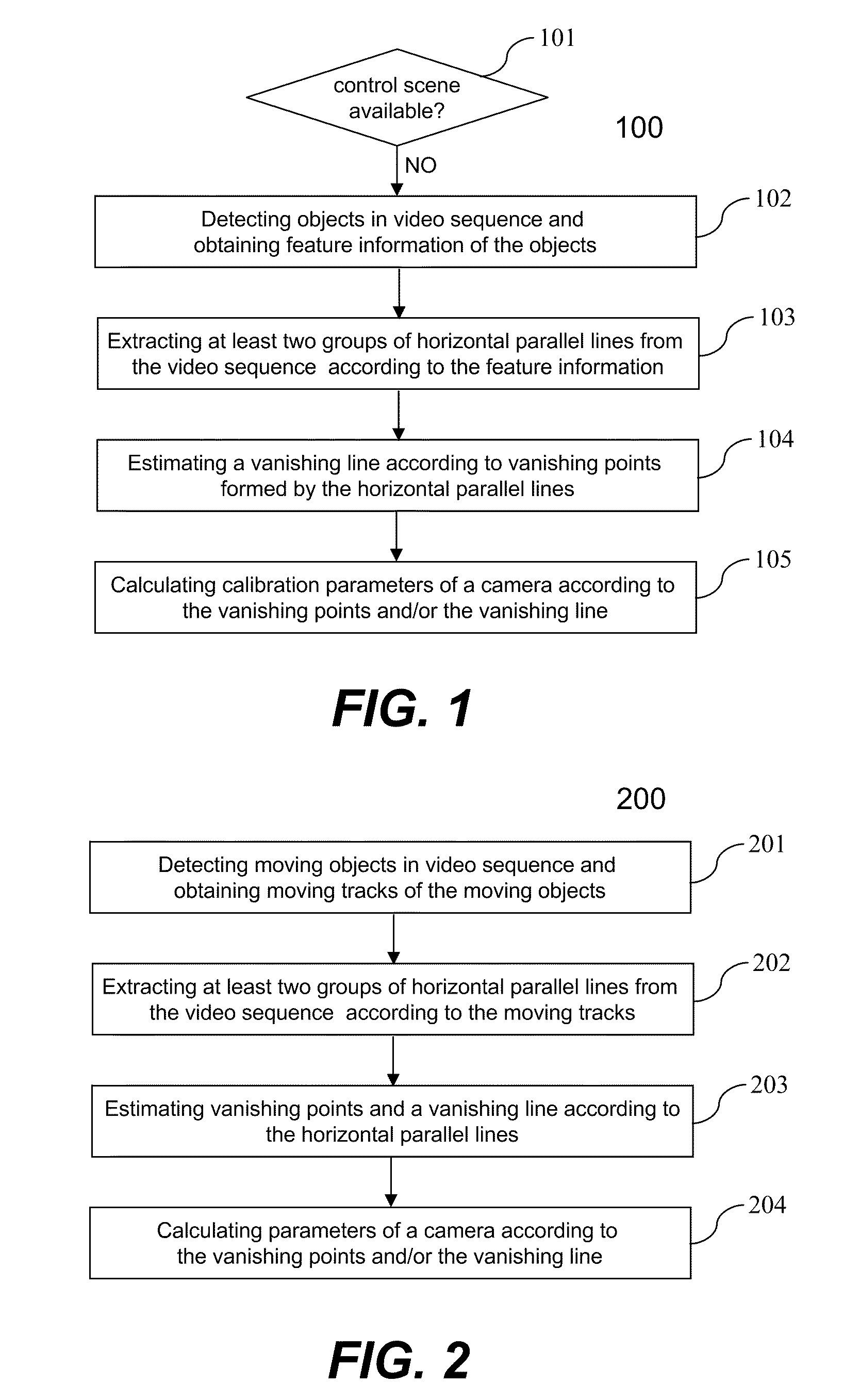
[0031]FIG. 1 is a flowchart or process 100 of showing camera calibration according to the present invention. The process 100 may be implemented in a processor in a camera. At 101, the process 100 checks whether a prearranged control scene is available for camera calibration. If no, the process 100 is taken to the operation at 102. If yes, a conventional camera calibration method based on the control scene is used to estimate the calibration parameters of the camera. In one embodiment, a control scene is an actual 3D control scene, and a classic numerical analysis algorithm may be provided to calculate the calibrate parameters. In another embodiment, a 2D control scene is prearranged in a plane for camera calibration when the objects of interest are located on the ground such as in the video surveillance application It requires only four control points in the 2D control scene to calculate the homography matrix between the ground plane in the image and the ground plane in the real spa...

second embodiment

[0038]FIG. 2 is a flowchart or process 200 for camera calibration according to the present invention. The process 200 may be implemented in a processor in a camera. At 201, moving objects are detected from video sequence captured by the camera and moving tracks of the moving objects are obtained. In one embodiment, the operation for detecting moving objects from video sequence comprises: establishing a background image of the video sequence which contains stationary objects of a scene; subtracting the background image from a current image which may contain moving objects; binarizing the difference image between the background image and the current image; analyzing connected components of the binarization image to obtain position and shape information of each moving object.

[0039]The moving tracks of the moving objects can be obtained by tracking the moving objects in the video sequence. Any conventional methods for tracking the moving objects can be used to obtain the moving tracks o...

fourth embodiment

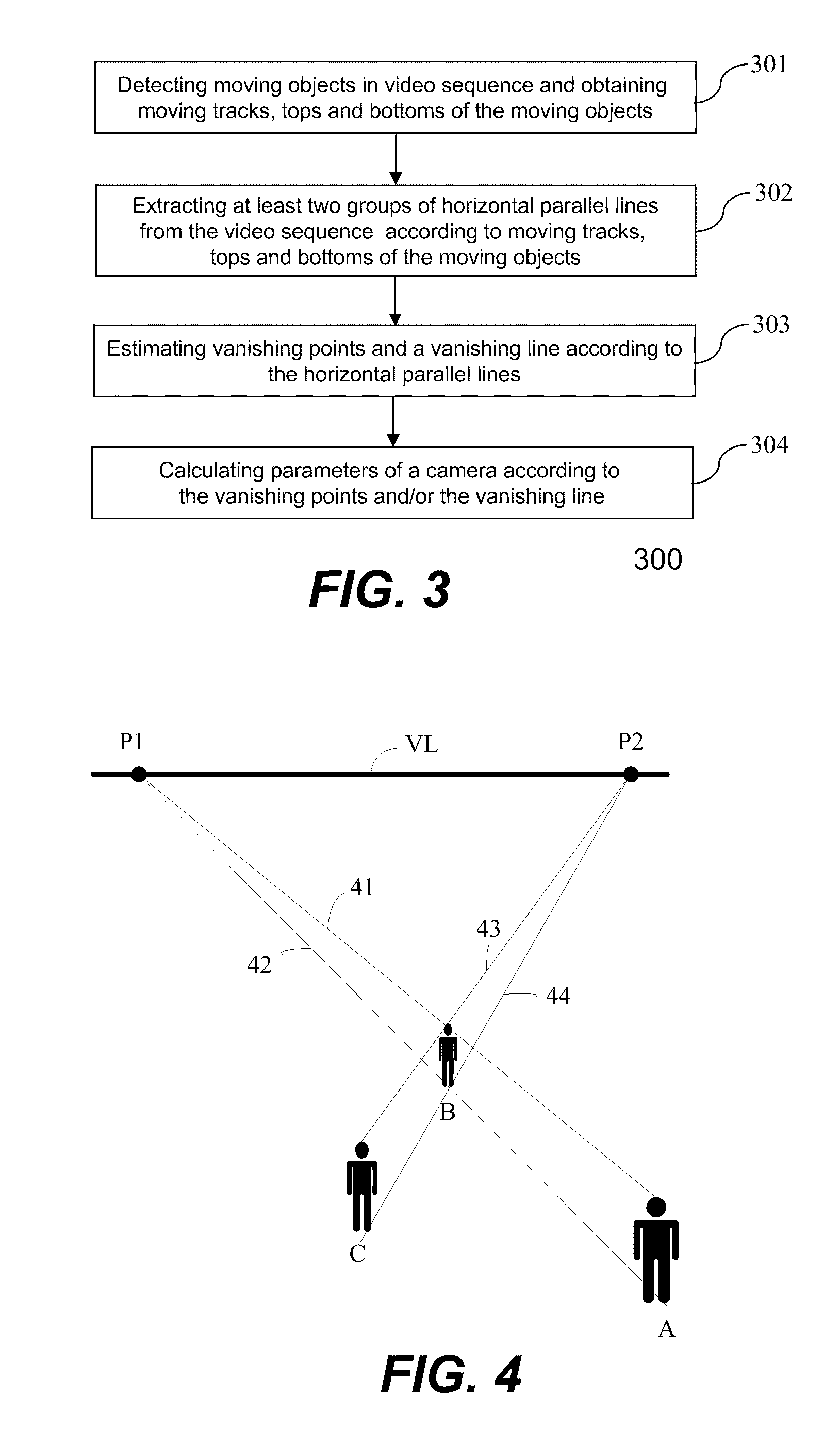
[0051]FIG. 5 is a flowchart or process 500 showing camera calibration according to the present invention. The process 500 may be implemented in a processor in a camera. At 501, objects with same height are detected from a video sequence. The positions, tops and bottoms of the moving objects are obtained. The objects with same height may be moving objects or stationary. E.g., the moving objects may be vehicles or walking human beings, and the stationary objects may be telegraph poles or footsteps.

[0052]At 502, at least two groups of perspective horizontal parallel lines are extracted from the video sequence according to the positions, the tops and the bottoms of the objects. A straight line connecting the tops and a straight line connecting the bottoms of two objects at different positions forms a group of perspective horizontal parallel lines because the two objects are at height. Thus, a plurality of perspective horizontal parallel lines can be obtained according to a plurality of ...


PUM


Abstract

Techniques pertaining to methods and devices for calibrating camera parameters are disclosed. According to one aspect of the present invention, objects on an image are detected and features on the objects, such as the top of a person, are identified. Perspective parallel lines based on the object features are constructed and vanishing points from the converged perspective parallel lines are determined. A vanishing line is defined according to the vanishing points. The intrinsic parameters, such as focal length, and the extrinsic parameters, such as tilting and pan angles, of a camera are calibrated according to the vanishing points, the vanishing line and a reference object with known dimensions, or known camera angles, The calibrated camera parameters are used for accurate photogrammetric measurements and computer vision applications.

Description

BACKGROUND OF THE INVENTION[0001]1. Field of the Invention[0002]The present invention relates to a field of camera calibration, more particularly to methods and devices for camera calibration from a single perspective image.[0003]2. Description of Related Art[0004]Camera calibration has always been an essential component of photogrammetric measurement and computer vision. Accurate camera calibration is necessary for extracting precise and reliable three-dimensional (3D) geometric information from two-dimensional (2D) plane images captured by a camera. Each 3D point in the 3D space may correspond to one 2D point in the 2D plane image captured by the camera. The relationship between the 3D points in the 3D space and the 2D points in the 2D plane image is represented as a perspective projection model of the camera. The perspective projection model comprises a plurality of intrinsic and extrinsic parameters of the camera. The intrinsic parameters are optical parameters of the camera, su...

Claims


Application Information

Patent Timeline
Patent Type & Authority Patents(United States)
IPC IPC(8): H04N9/47H04N5/225H04N17/02H04N17/00G06T7/00H04N7/18
CPCG06T7/0018G06T2207/10016G06T7/80
Inventor XIE, DONGHAIWANG, LEI
Owner VIMICRO CORP
Why Eureka
Try Eureka