Light guide plate and surface light source device

a surface light source and light guide plate technology, applied in mechanical devices, lighting and heating devices, instruments, etc., can solve the problems of impairment of the split light-emission property, more than necessary power consumption, and low light-emission efficiency, and achieve stable output light and reduce light-emission efficiency

Active Publication Date: 2014-11-11
PANASONIC CORP
View PDF9 Cites 6 Cited by
  • Summary
  • Abstract
  • Description
  • Claims
  • Application Information

AI Technical Summary

Benefits of technology

[0019]However, with the above-described structure of Document 1, since each prism (tetrahedral lens 226) is made up from regions of the outgoing surface 223 adjacent to the incident surface 221, widened placement intervals of LEDs would cause bright / dark portions to occur in portions of the outgoing surface 223 in vicinities of the incident surface 221 due to influences of the directivity of the LEDs. Besides, setting outer dimensions of the light guide plate 22 equal to the effective light-emission area would cause the light guide plate 22 to be expanded and contracted by influences of heat of the LEDs, so that it may become impossible to output light stably from the effective light-emission area. Therefore, it is desirable that the outer dimensions of the light guide plate 22 be larger than the effective light-emission area. In such a case, with the prism shapes present outside the effective light-emission area, light that is originally not intended for use in the liquid crystal display device would be outputted to the outgoing surface 223 in the prism shape regions. As a result, use efficiency of light would lower, involving more than necessary power consumption.
[0021]Accordingly, an object of the present invention, lying in solving the above-described problems, is to provide a light guide plate capable of suppressing the occurrence of hot spots and bright / dark lines without impairing the split light-emission property.
[0035]As described above, according to the light guide plate of the invention, it becomes implementable to suppress hot spots and bright / dark lines without impairing the split light-emission property.

Problems solved by technology

As a result, use efficiency of light would lower, involving more than necessary power consumption.
Such light is seen as an afterimage in the screen so as to deteriorate the screen quality, leading to an impairment of the split light-emission property.

Method used


Image

  • Light guide plate and surface light source device
  • Light guide plate and surface light source device
  • Light guide plate and surface light source device

Examples


embodiment 1

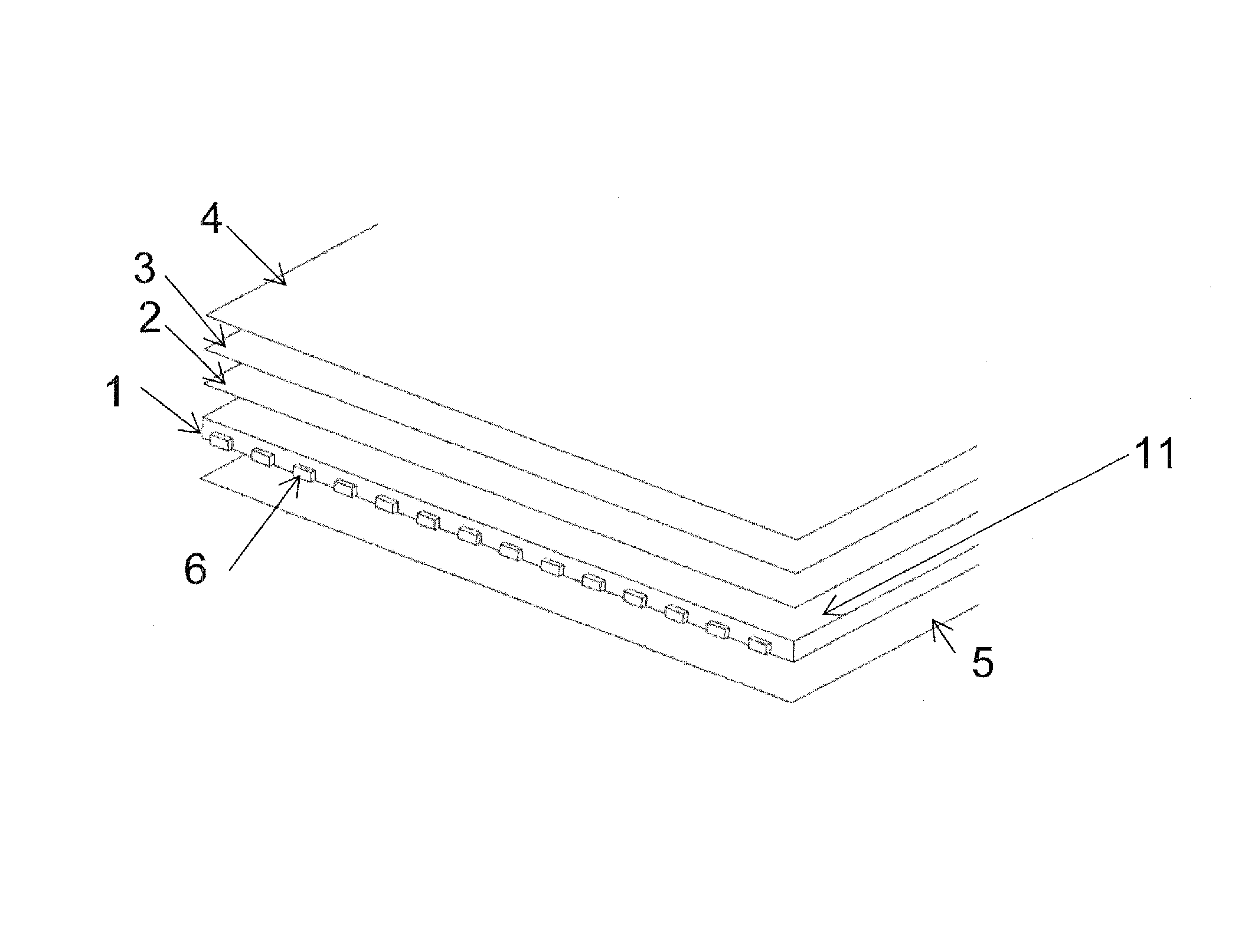
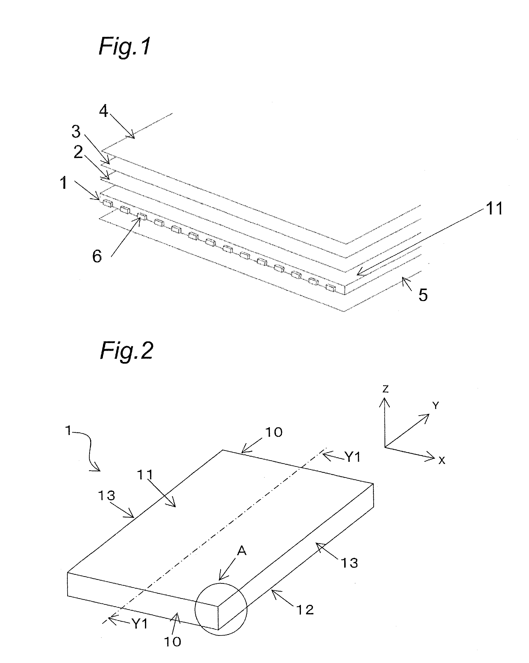
[0076]Embodiment 1 of the invention is described with reference to FIGS. 1 to 21. FIG. 1 is a schematic view showing a surface light source device according to Embodiment 1. As shown in FIG. 1, the surface light source device includes a light guide plate 1, a diffusion sheet 2, a prism sheet 3, an optical sheet 4, a reflecting sheet 5, and LEDs 6. The light guide plate 1 is formed from a transparent resin (e.g., acrylic resin or polycarbonate) or the like. The diffusion sheet 2 for diffusing light outputted from the upper surface of the light guide plate 1 is provided above the light guide plate 1. The diffusion sheet 2 may be made up by dispersing materials of different refractive index inside a sheet of transparent resin or the like, or by dispersing a transparent spherical-shaped material on a transparent sheet, or by forming depressions and projections on a surface of a transparent sheet.

[0077]With an aim of achieving higher luminance by converging light outputted from the diffu...

embodiment 2

[0131]A surface light source device according to Embodiment 2 of the invention is described below with reference to FIGS. 22 to 27.

[0132]FIG. 22 shows a light guide plate 21 according to this Embodiment 2, and FIGS. 23 and 24 are a perspective view and a top view, respectively, of B part of FIG. 22 in the light guide plate 21. In FIG. 22, an outgoing surface 31 is a surface from which light incident from the incident surface 10 is outputted. The surface light source device according to this Embodiment 2 differs from the surface light source device (FIG. 2) of Embodiment 1 only in the configuration of the outgoing surface of the light guide plate, the rest of the structure being similar to that of Embodiment 1. More specifically, in this Embodiment 2, two groups of prism protrusions are provided in the outgoing surface, and a placement ratio of those groups is changed depending on the LED placement pitch and the total luminous flux per LED.

[0133]As shown in FIG. 23, the two groups of...


PUM


Abstract

A light guide plate includes an incident surface on which light outputted from point light sources is incident and an outgoing surface for outputting light incident from the incident surface, wherein a reflection-and-propagation surface for reflecting light toward the outgoing surface is formed in a back surface opposite to the outgoing surface. The outgoing surface is made up of a propagation region adjacent to the incident surface, a diffusion-and-propagation auxiliary region adjacent to the propagation region, and a diffusion-and-propagation region adjacent to the diffusion-and-propagation auxiliary region. Hot spots and bright / dark lines in vicinities of the incident surface are controlled primarily by curved portions of prism upper ends formed in the diffusion-and-propagation region, and viewing-angle characteristics of the light guide plate are controlled primarily by linear portions of the prisms.

Description

BACKGROUND OF THE INVENTION[0001]1. Field of the Invention[0002]The present invention relates chiefly to a surface light source device to be used in backlight units of liquid crystal display panels or the like.[0003]2. Description of the Related Art[0004]In recent years, liquid crystal display devices have been rapidly expanding in application range by virtue of their features such as light weight, thin thickness and low power consumption drive. Liquid crystal display devices, which are not self light-emitting devices, generally need a separate light source such as a backlight. A backlight unit is composed mainly of a light source and a light guide plate for guiding light outputted from the light source to provide surface emission.[0005]Generally, backlight units can be classified into direct type, edge light type, or the like depending on the position of the light source. With a direct type backlight unit, a multiplicity of light sources, e.g. cold-cathode tubes or LEDs (Light Emit...

Claims


Application Information

Patent Timeline
Patent Type & Authority Patents(United States)
IPC IPC(8): F21V8/00
CPCG02B6/0068G02B6/0038G02B6/0045
Inventor KIKUCHI, TAKANORIITO, MASAMIFUJITA, MASARUKUSAKA, YUSUKE
Owner PANASONIC CORP
Why Eureka
Try Eureka