Orthopedic clamp and extension rod

a technology of extension rod and orthopedic clamp, which is applied in the field of orthopedic clamp and extension rod, can solve the problems of increasing the cost and time of spinal surgery, adding patients' problems,

Active Publication Date: 2014-11-11
GLOBUS MEDICAL INC
View PDF61 Cites 228 Cited by
  • Summary
  • Abstract
  • Description
  • Claims
  • Application Information

AI Technical Summary

Problems solved by technology

However, adjacent segment disease and other conditions may require revisions requiring a surgeon to remove the entire spinal implant and position new implants to further support and stabilize the spinal components of the anatomy.
The removal of the original spinal implant and the subsequent positioning of new implants may cause additional problems for the patient and increases the cost and time of spinal surgeries.

Method used


Image

  • Orthopedic clamp and extension rod
  • Orthopedic clamp and extension rod
  • Orthopedic clamp and extension rod

Examples


Embodiment Construction

[0013]Embodiments of the invention will now be described. The following detailed description of the invention is not intended to be illustrative of all embodiments. In describing embodiments of the present invention, specific terminology is employed for the sake of clarity. However, the invention is not intended to be limited to the specific terminology so selected. It is to be understood that each specific element includes all technical equivalents that operate in a similar manner to accomplish a similar purpose.

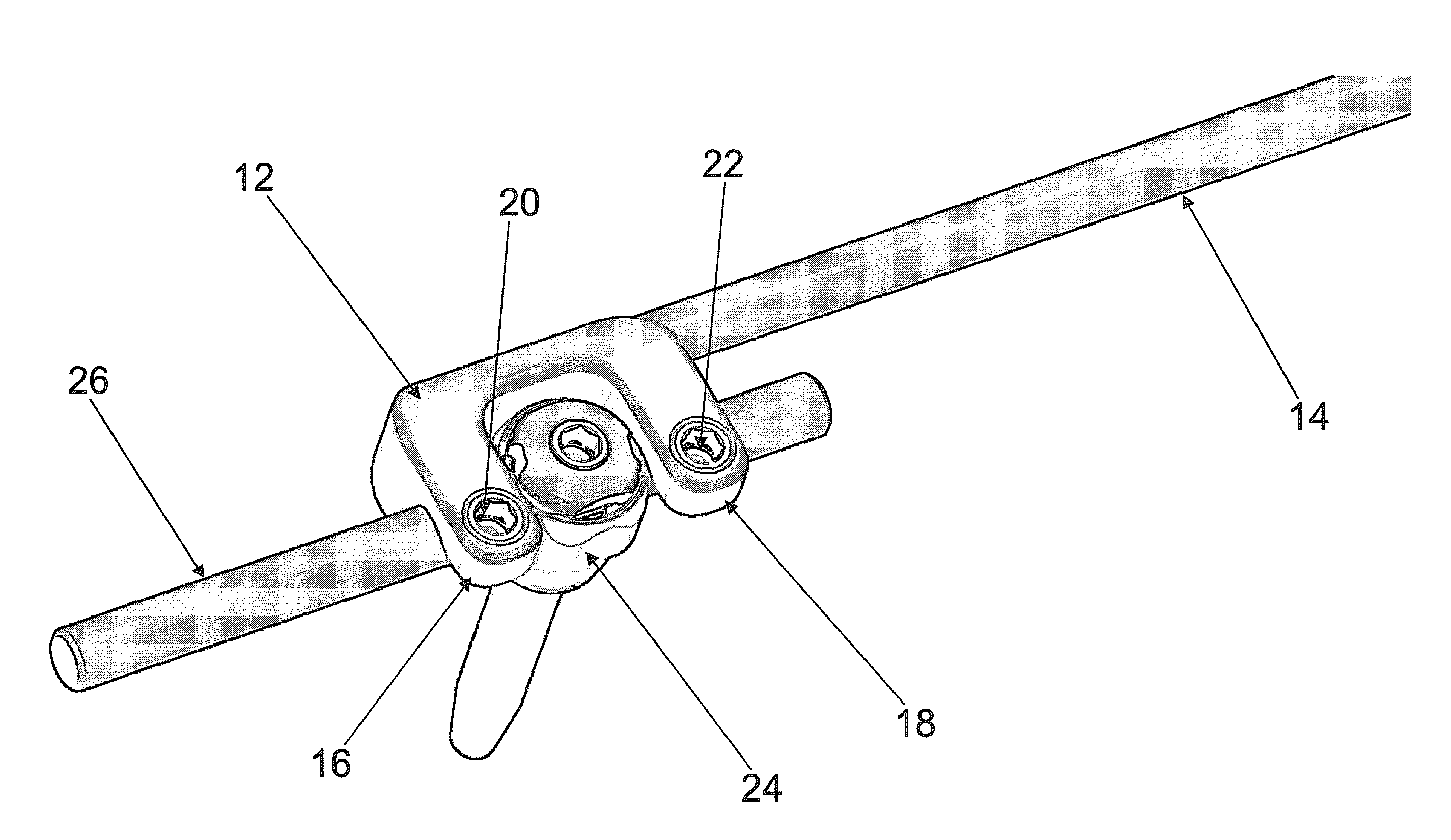
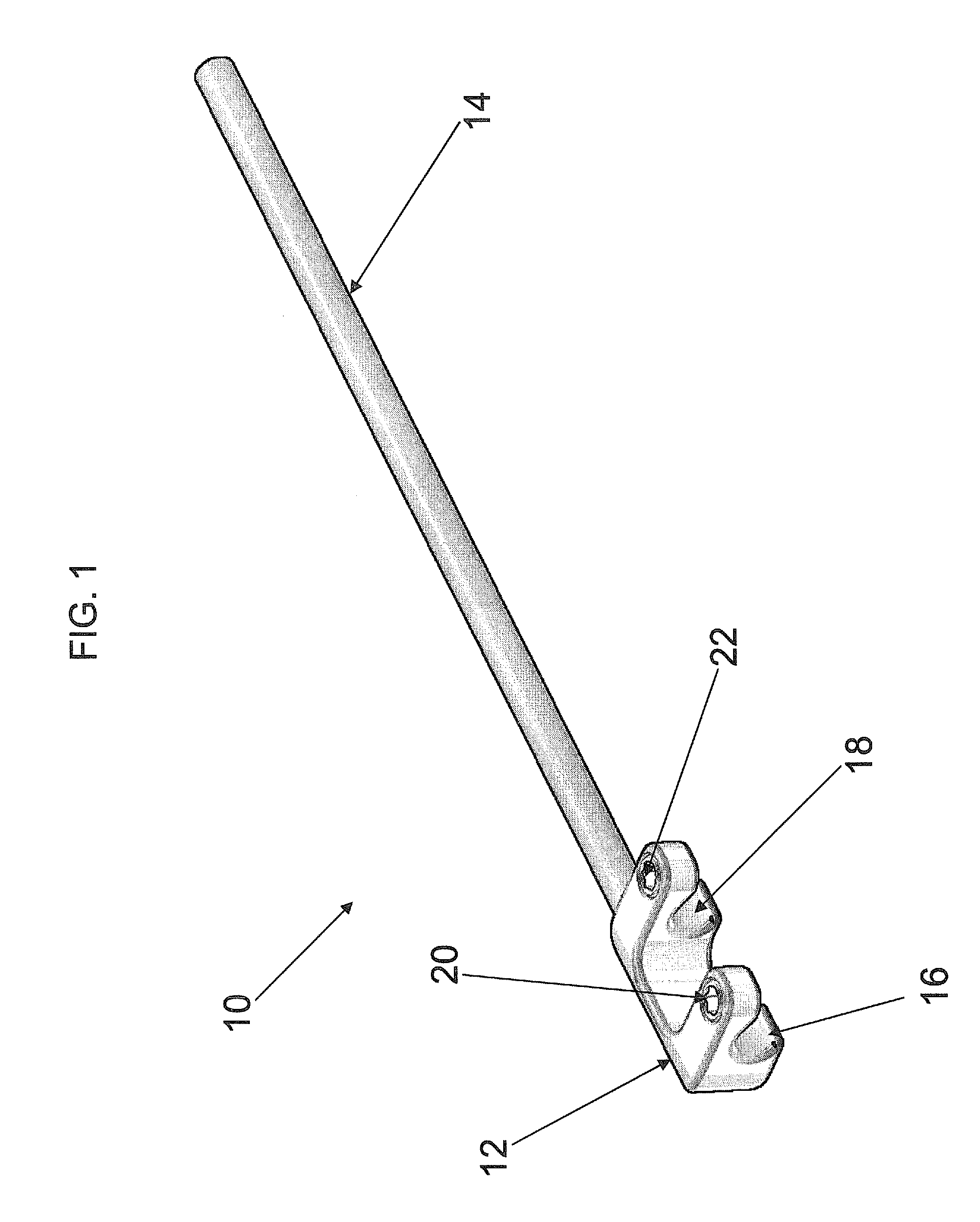
[0014]FIG. 1 illustrates the extension clamp 10 according to one embodiment of the present invention. The clamp 10 as shown is configured and dimensioned having a yoke 12 and an integrated rod 14. As clearly illustrated in FIG. 1, the yoke 12 and the rod 14 of the clamp 10 are integrated as a single piece. The yoke 14 is merged or integrated with the rod 12 that is preferably 160 millimeters long and having a diameter of 5.5 millimeters. However, the rod 12 may be shaped an...


PUM


Abstract

A spinal implant for connecting to an elongated rod is disclosed. The spinal implant includes a yoke having a first end and a second end, the first end having a first and second rod engaging portion and a channel between the first and second rod engaging portions for encompassing a first bone anchor, and the second end being spaced apart from the first end. An extension rod is also provided which extends from the second end of the yoke parallel to the elongated rod. The first and second rod engaging portions are configured and dimensioned to receive first and second securing member for securing the elongated rod.

Description

FIELD OF THE INVENTION[0001]The present invention relates to a spinal implant that stabilizes and supports the spine.CROSS-REFERENCE TO RELATED APPLICATIONS[0002]All publications and patent applications mentioned in this specification are herein incorporated by reference to the same extent as if each individual publication or patent application was specifically and individually indicated to be incorporated by reference.BACKGROUND OF THE INVENTION[0003]Spinal deformities, spinal injuries, and other spinal conditions may be treated with the use of spinal implants. Spinal implants are designed to support the spine and properly position the components of the spine. One such spinal implant includes an elongated rod and a plurality of bone anchors. The elongated rod is positioned to extend along one or more of the components of the spine and the bone anchors are attached to the spinal components at one end and secured to the elongated rod at the other end.[0004]However, adjacent segment d...

Claims


Application Information

Patent Timeline
Patent Type & Authority Patents(United States)
IPC IPC(8): A61B17/70
CPCA61B17/705A61B17/7002
Inventor IOTT, ANDREWFRIEDRICH, ADAMCAHILL, DOUGLASJUCHNO, BRADSALZBERGER, MARK
Owner GLOBUS MEDICAL INC
Why Eureka
Try Eureka