Spinal implant and method for restricting spinal flexion

a technology of spinal flexion and spinal implants, applied in the field of spinal implants, can solve the problems of affecting patients' ability to work and otherwise enjoy their lives, discogenic pain can be quite disabling, and current treatment options for patients diagnosed with chronic discogenic pain are quite limited

Active Publication Date: 2008-12-02
THE BOARD OF TRUSTEES OF THE LELAND STANFORD JUNIOR UNIV
View PDF99 Cites 283 Cited by
  • Summary
  • Abstract
  • Description
  • Claims
  • Application Information

AI Technical Summary

Problems solved by technology

Discogenic pain can be quite disabling, and for some patients it dramatically affects their ability to work and otherwise enjoy their lives.
Current treatment alternatives for patients diagnosed with chronic discogenic pain are quite limited.
Fusion is not typically recommended for discogenic pain because it is irreversible, costly, associated with high morbidity, and of questionable effectiveness.
Despite its drawbacks, however, spinal fusion for discogenic pain remains common due to the lack of viable alternatives.

Method used


Image

  • Spinal implant and method for restricting spinal flexion
  • Spinal implant and method for restricting spinal flexion
  • Spinal implant and method for restricting spinal flexion

Examples


first embodiment

[0023]Referring to FIG. 2, a spinal implant comprises an elastic or semi-elastic band 20 sized to be positionable around adjacent spinous processes 10. Once implanted, the band 20 limits the amount of spreading between spinous processes 10 upon spinal flexion. Thus, when the patient bends the band 20 is placed in tension, thereby restricting posterior tension that would otherwise be experienced by the dorsal annulus and limiting the amount of flexion that can be achieved. Thus, the intervertebral disc is subjected to limited bending forces and pain is therefore reduced or eliminated. In this capacity, the band functions as an artificial ligament, supplementing the supraspinous and interspinous ligaments, which are normally loaded during flexion.

[0024]As best shown in FIG. 3A, band 20 includes an elongate portion 22 having ends 24a, 24b and a connector 26 for coupling the ends 24a, 24b to form the band into a loop. The connector 26 includes a housing 27 having a keyway opening 28 at ...

third embodiment

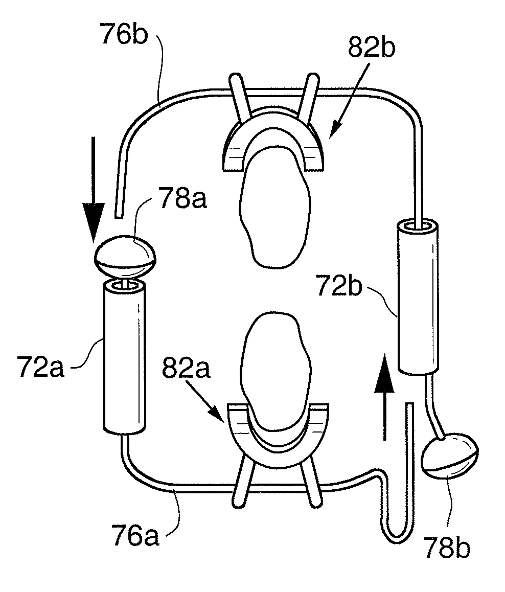
[0041]Components of a spinal implant 70 are illustrated in FIG. 7. Implant 70 is similar to the prior embodiments in that, when assembled, it takes the form of a band positionable around the spinous processes. However, it differs from prior embodiments in that it restricts spinal flexion using compression elements that are placed in compression upon expansion of the band during spinal flexion.

[0042]Referring to FIG. 7, implant 70 includes a pair of elastomeric members 72a, 72b, each of which includes a throughbore 74a, 74b and a cable 76a, 76b extending through the throughbore. Cables 76a, 76b are preferably inelastic, although in an alternative embodiment elastic cables may also be used. The elastomeric members may be housed in an enclosure or casing 86 (FIG. 9) formed of a biocompatible metal (e.g. titanium or stainless steel) or polymer, if desired. Casing 86 includes a removable cap 88 which mates with the casing using threaded connections. Openings 89a, 89b are provided in the ...


PUM


Abstract

A spinal implant system for restricting flexion of a spine includes an elongate band proportioned to engage at least two spinous processes. During use, the band is positioned engaging the spinous processes at a spinal segment of interest, where it restricts flexion at the segment. The length and tension of the band may be adjustable following to implantation using percutaneous or transcutaneous means.

Description

PRIORITY[0001]This application claims the benefit of U.S. Provisional Application No. 60 / 551,235, filed Mar. 9, 2004, which is incorporated herein by reference.FIELD OF THE INVENTION[0002]The present invention relates generally to the field of spinal implants and more particularly to the field of implants for restricting spinal flexion.BACKGROUND OF THE INVENTION[0003]A major source of chronic low back pain is discogenic pain, which is also known as internal disc disruption. Patients suffering from discogenic pain tend to be young (30-50 years of age), otherwise healthy individuals who present with pain localized to the back. Usually discogenic pain occurs at the discs located at the L4-L5 or L5-S1 junctions. Pain tends to be exacerbated when patients put their lumbar spines into flexion (i.e. by sitting or bending forward) and relieved when they put their lumbar spines into extension (i.e. arching backwards). Discogenic pain can be quite disabling, and for some patients it dramatic...

Claims


Application Information

Patent Timeline
Patent Type & Authority Patents(United States)
IPC IPC(8): A61B17/70A61B17/58
CPCA61B17/7062
Inventor FIELDING, LOUIEBENNETT, IANCAHILL, COLINARENSDORF, PATCRISOSTOMO, RALPHALAMIN, TODD
Owner THE BOARD OF TRUSTEES OF THE LELAND STANFORD JUNIOR UNIV
Why Eureka
Try Eureka