Expandable spinal implants

a technology of expanding spinal implants and expanding spines, applied in the field of expanding spinal implants, can solve problems such as pain in the affected sid

Inactive Publication Date: 2001-04-17
KOROS TIBOR
View PDF4 Cites 304 Cited by
  • Summary
  • Abstract
  • Description
  • Claims
  • Application Information

AI Technical Summary

Problems solved by technology

This usually causes pain in the affected side.
Some surgeons are apprehens...

Method used


Image

  • Expandable spinal implants
  • Expandable spinal implants
  • Expandable spinal implants

Examples


Embodiment Construction

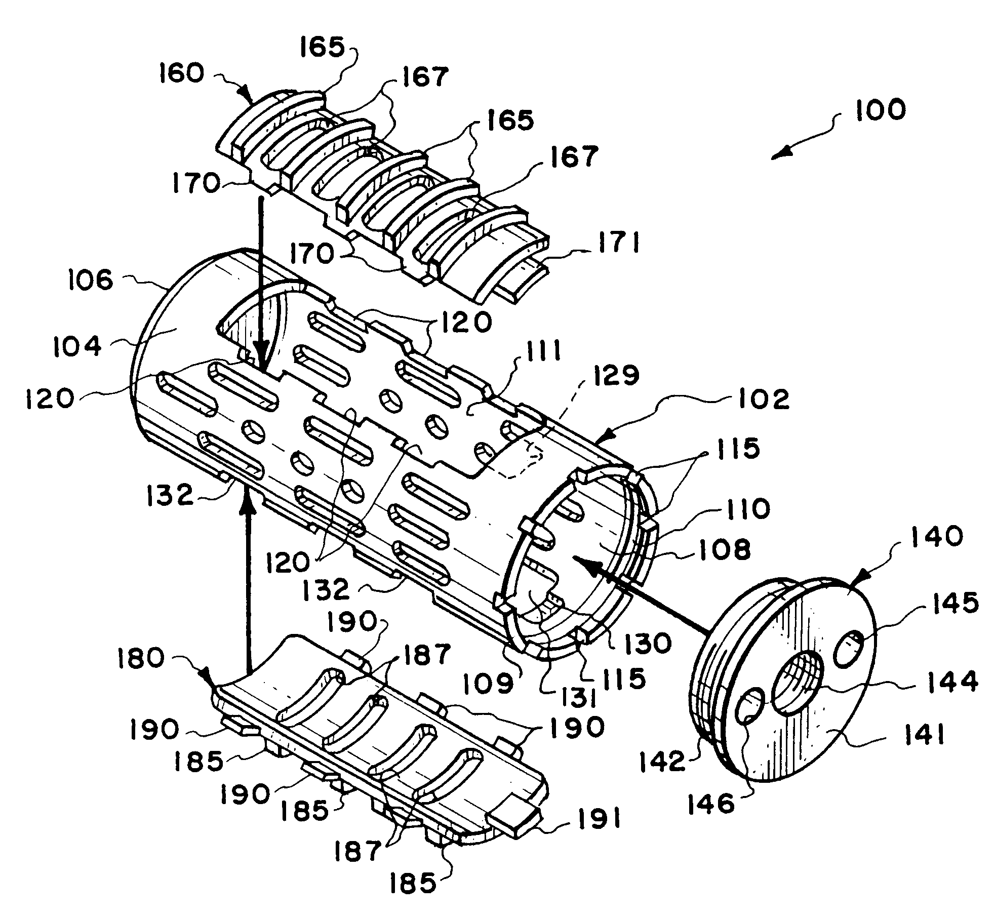
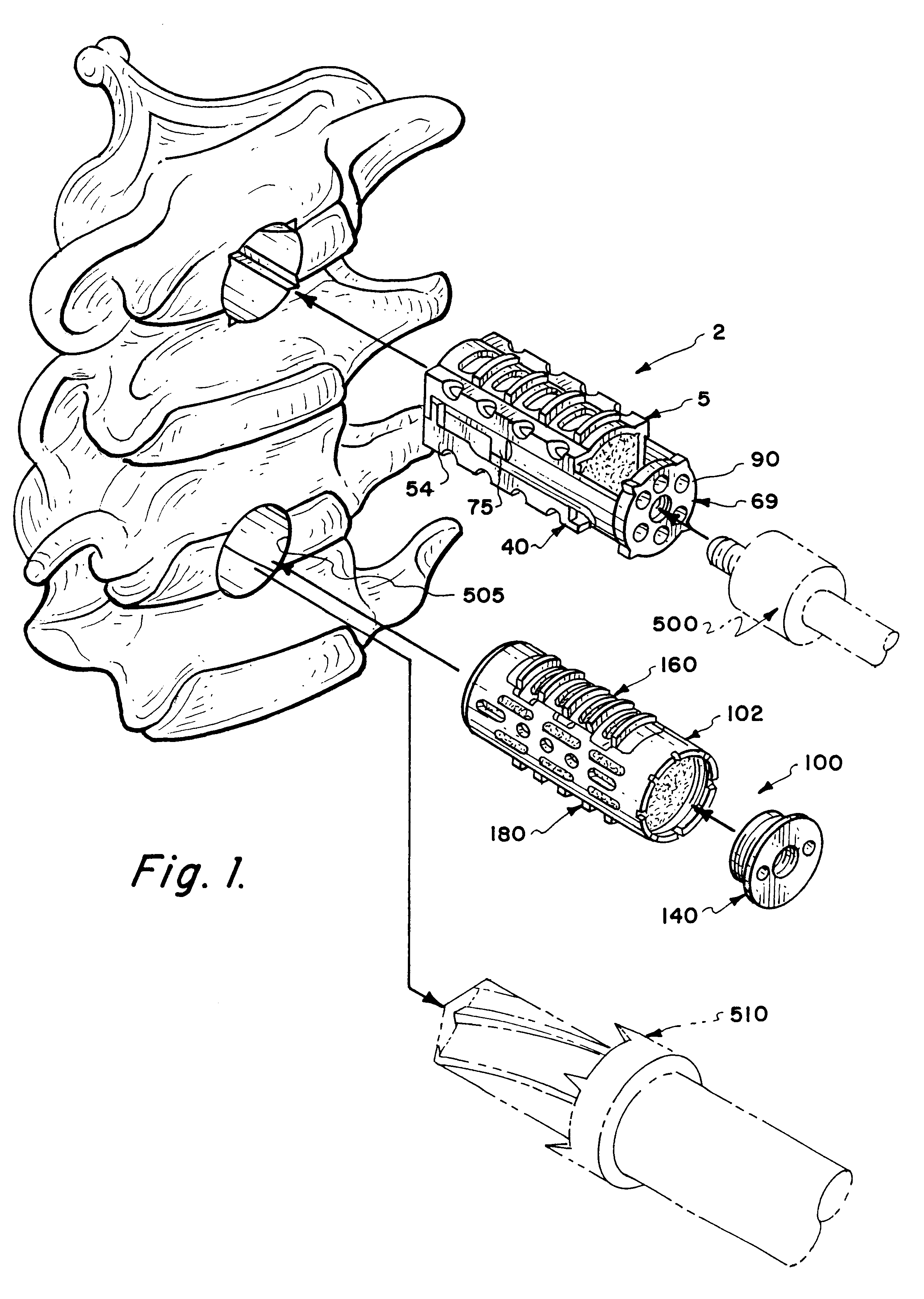
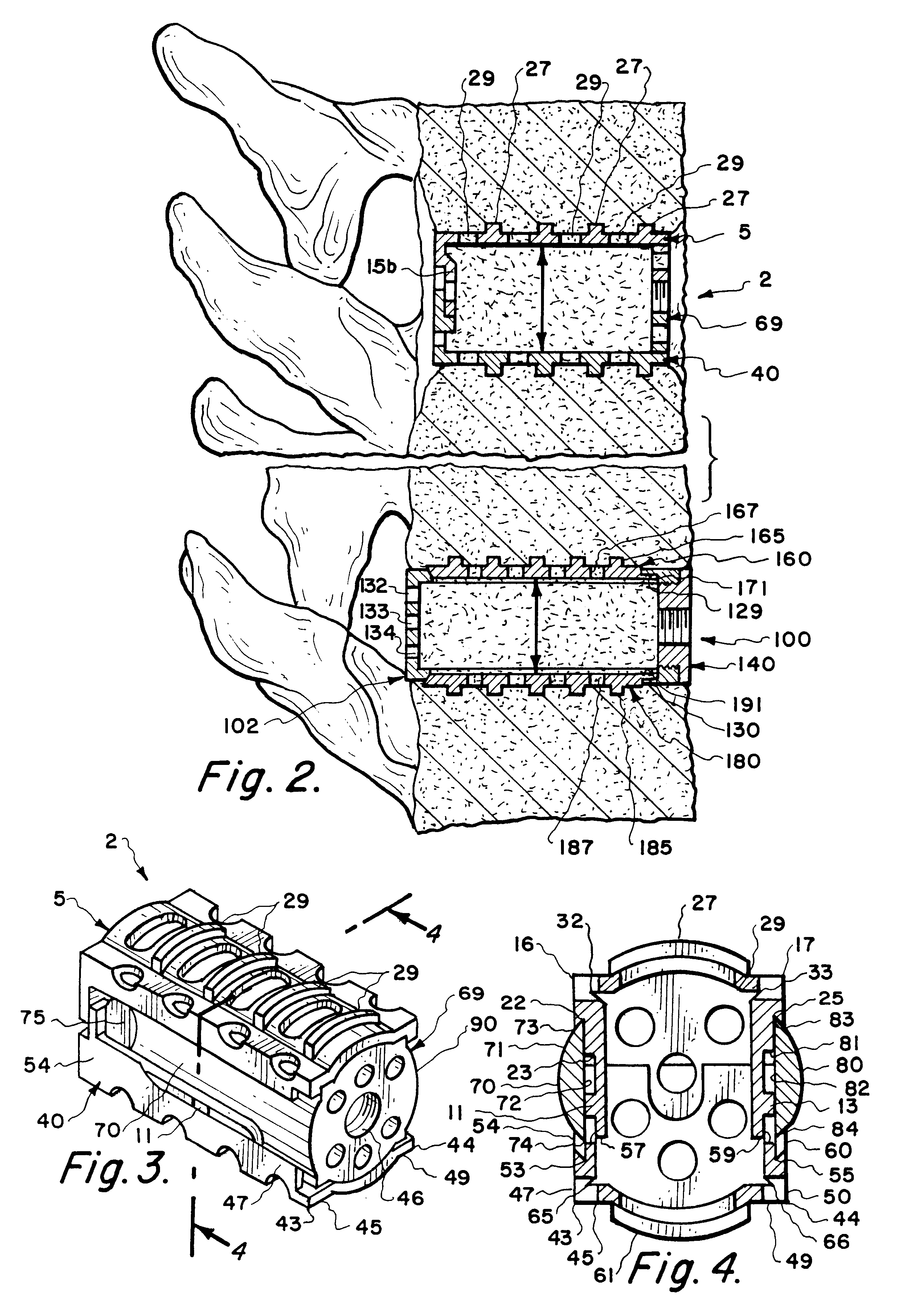
The present invention will now be discussed in greater detail. FIGS. 1 and 2 illustrate the first two embodiments in relation to the patient's spine. FIGS. 1-5 illustrate the first embodiment of the present spinal implant invention. The first embodiment which is labelled number 2 in the drawings is an expandable spinal implant as are the other three implants comprising the present invention and described herein. The first embodiment 2 is referred to as the box implant and includes three interlocking parts, which are clearly illustrated in the perspective exploded view in FIG. 5. The three interlocking parts are the superior section 5, the inferior section 40, and the U-shaped expander cap 69. When the three parts interlock, the implant is symmetrical about its vertical medial longitudinal axis. This symmetry also applies to each of the three parts. The superior section 5, the inferior section 40 and the cap 70 are each symmetrical about their respective vertical medial longitudinal ...


PUM


Abstract

A cylinder-shaped expandable spinal implant is disclosed. The implant is a hollow housing having a cylinder-shaped wall, with a circular sealed distal end, and an opposite proximal circular open end. The open end of the housing has internal threads for securing a cap to it. A removable cap is threaded on the open end of the housing. The housing has two opposite large rectangular openings located longitudinally in the wall of the housing for receiving two arcuate sections. Each arcuate section is positioned in the rectangular opening in the wall of the implant. A locking means for locking the arcuate section in the rectangular opening in the wall is provided. A plurality of small ports are drilled in the wall for allowing bone growth after implantation of said implant in a patient. The arcuate sections have transverse ribs for locking the implant in position are implantation. Openings between the ribs are provided for allowing bone growth.

Description

1. Field of the InventionThe present invention pertains to the following areas of technology:PROSTHESIS (I.E., ARTIFICIAL BODY MEMBERS), PARTS THEREOF OR AIDS AND ACCESSORIES THEREFOR; implantable prosthesis for the spinal column such as vertebrae and spinal discs for example.2. Description of the Prior ArtU.S. Pat. No. 4,501,269 issued to Bagby on Feb. 26, 1985 discloses a basket-type of spinal implant.U.S. Pat. No. 4,961,740 issued on Oct. 9, 1990 to Ray and U.S. Pat. No. 5,055,104 issued on Oct. 8, 1991 also issued to Ray disclose a coil-type of spinal implant.U.S. Pat. No. 5,015,247 issued on May 14, 1991 to Michelson discloses a threaded spinal implant.In the early 1950's an operation was pioneered by Ralph B. Cloward, M.D. for the removal of ruptured cervical disc lesions and osteophytes by an anterior surgical approach. A herniated disc is a rupture or herniation of the intervertebral disc, especially between lumbar vertebrae. This usually causes pain in the affected side. An...

Claims


Application Information

Patent Timeline
IPC IPC(8): A61F2/30A61F2/44A61B17/16A61F2/28A61F2/00A61F2/46
CPCA61F2/30744A61F2/4455A61F2/446A61B17/1671A61F2/442A61F2/4611A61F2002/2835A61F2002/30235A61F2002/30271A61F2002/30405A61F2002/30579A61F2002/30774A61F2002/30777A61F2002/30785A61F2002/30787A61F2002/30879A61F2002/4475A61F2002/449A61F2220/0025A61F2230/0069A61F2230/0082A61F2002/30261A61F2002/30593
Inventor KOROS, TIBOR
Owner KOROS TIBOR
Why Eureka
Try Eureka