Method and apparatus for providing posterior or anterior trans-sacral access to spinal vertebrae

a transsacral and spinal vertebrae technology, applied in the direction of prosthesis, surgical forceps, therapy, etc., can solve the problems of high failure rate of fusion procedure, neurologic deficit in nerve function, extreme pain, etc., to reduce discomfort for patients, minimally invasive

Inactive Publication Date: 2006-08-08
MIS IP HLDG LLC
View PDF168 Cites 292 Cited by
  • Summary
  • Abstract
  • Description
  • Claims
  • Application Information

AI Technical Summary

Benefits of technology

[0040]The access procedures for forming the anterior or posterior percutaneous tract and the subsequently conducted surgical repair and/or implantation procedures are minimally invasive and requires a short, if any, post-implantation hospitalization and recovery period and reduced discomfort to the patient. The access procedures avoid the muscle stripping required to access the vertebrae and/or discs or removal of strong anterior vertebral body bone and intervening discs attendant to the conventional lateral surgical approaches described above
[0041]The anterior and posterior TASIF approaches also allow disc surgery or disc augmentation through the TASIF bore or pilot hole of all discs traversed by the TASIF axial bore or pilot hole in a minimally invasive manner. Moreover, these approaches can be employed a minimally invasive manner to perform vertebroblasty of the vertebrae traversed by the TASIF axial bore or pilot hole to augment the vertebral bone in cases of compression fracture of the vertebral bone. Vertebroblasty is procedure for augmentation of collapsed vertebral bodies by pumped in materials, e.g., bone cement. In the past, it has been accomplished through a lateral approach of a needle into a single vertebral body

Problems solved by technology

Patients who suffer from such condition usually experience extreme and debilitating pain and often neurologic deficit in nerve function.
Although the initial proponents of this approach report 90% excellent to good results, subsequent studies have been unable to obtain acceptable outcomes and recommend adding internal fixation to improve fusion rates.
However, when generally used by practicing surgeons, the procedure was found to have a high failure rate of fusion.
Attempts to increase the fusion rate by performing a posterior stabilization procedure have been successful, but the second incision increases the morbidity and decreases the advantages of the technique.
Thus, the present surgical techniques available to remove and fuse painful lumbar discs are extensive operative procedures with potentially significant complications.
There is no single procedure which is universally accepted to surgically manage low back pain patients.
Although damaged discs and vertebral bodies can be identified with sophisticated diagnostic imaging, the surgical procedures are so extensive that clinical outcomes are not consistently satisfactory.
Furthermore, patients undergoing presently available fusion surgery experience uncomfortable, prolonged convalescence.
However, there are still disadvantages to the present fixation implants and surgical implantation tech

Method used


Image

  • Method and apparatus for providing posterior or anterior trans-sacral access to spinal vertebrae
  • Method and apparatus for providing posterior or anterior trans-sacral access to spinal vertebrae
  • Method and apparatus for providing posterior or anterior trans-sacral access to spinal vertebrae

Examples


first embodiment

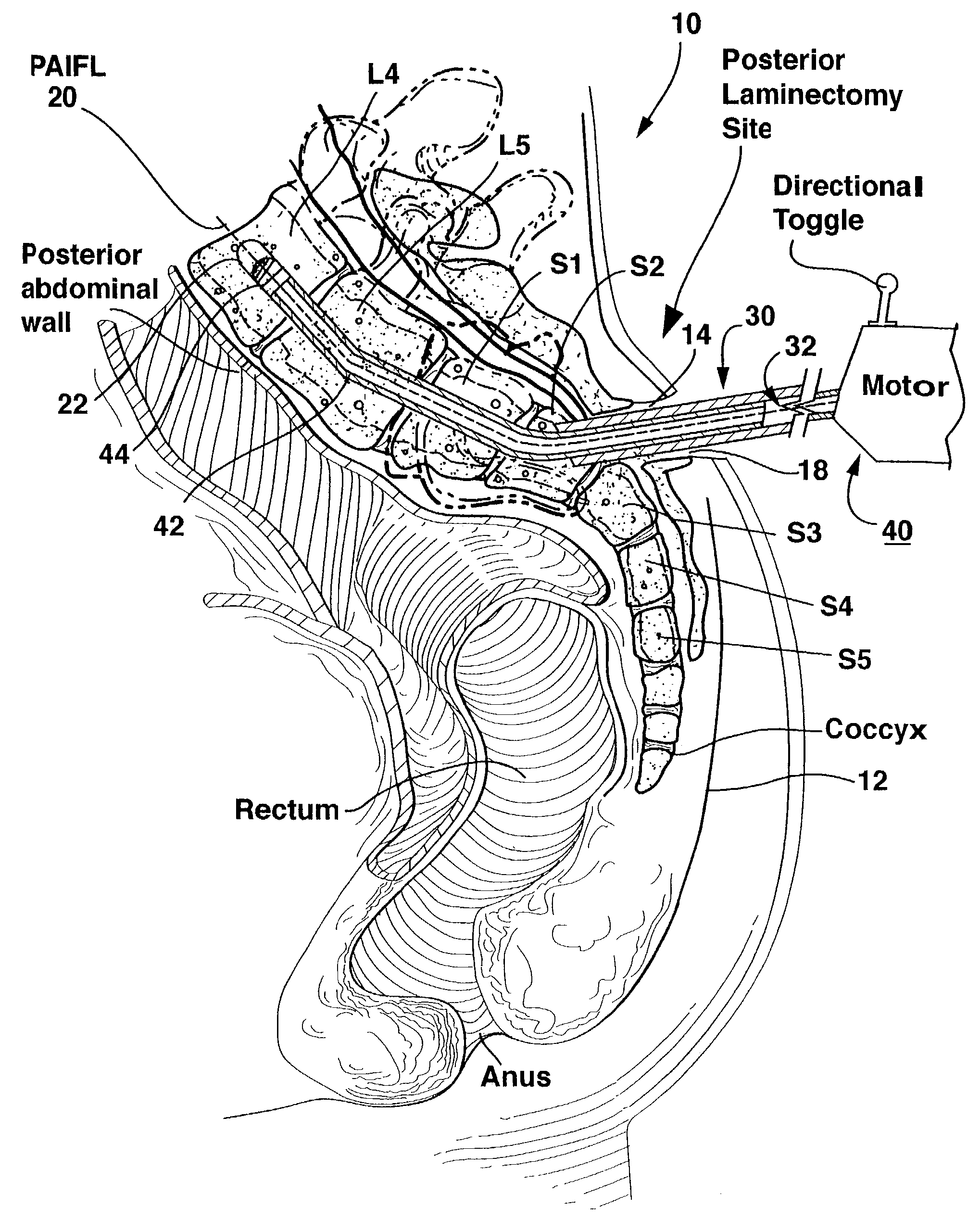
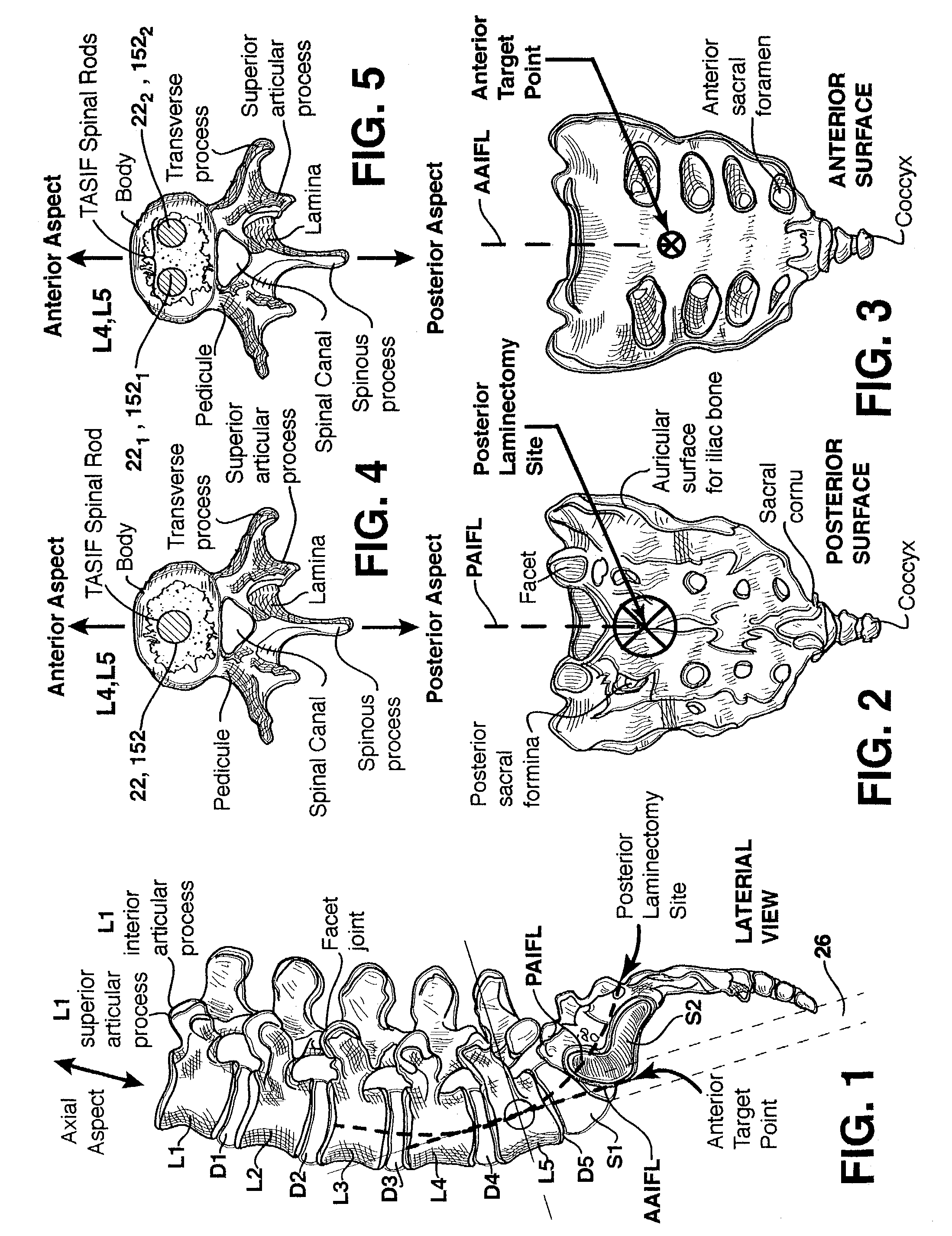
[0113]In use of the first embodiment, the enlarged diameter anterior tract sheath 96 is advanced through the presacral space 24 over the inflated balloon 90 or the dilator(s) 340, 350, and the beveled distal end 97 is aligned with the typical angle of the anterior surface of the sacrum at the anterior target point as shown in FIG. 28. The anterior tract sheath 96 is thereby axially aligned with the AAIFL, and the anterior tract sheath lumen 98 forms the anterior tract 26 shown in FIG. 1.

second embodiment

[0114]In use of the second embodiment, the anterior tract sheath 196 is advanced through the presacral space 24 over the inflated balloon 90 or the dilator(s) 340, 350 as shown in FIG. 30, and the threaded tip distal end 197 is screwed into the sacral bone at the anterior target point as shown in FIG. 31. The anterior tract sheath 196 is thereby axially aligned with the AAIFL, and the anterior tract sheath lumen 198 forms the anterior tract 26 shown in FIG. 1.

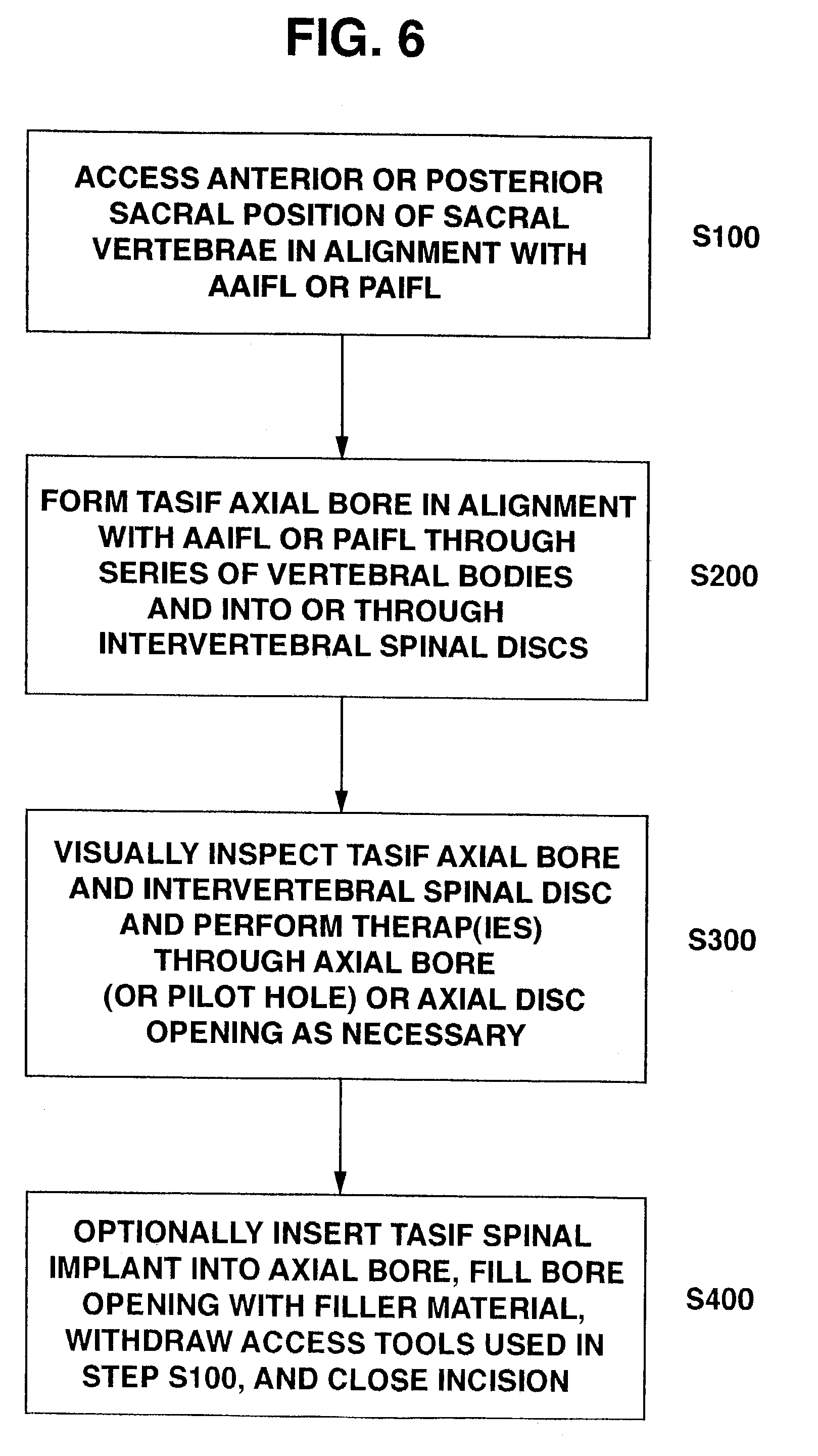
[0115]The balloon 90 is then deflated, and the balloon catheter 84 and the guidewire 80 are withdrawn from tract sheath lumen 98, 198. Alternatively, the dilator(s) 340, 350 and the guidewire 80 are withdrawn from tract sheath lumen 98. The anterior tract 26 of the anterior tract sheath 96, 196 is employed in the steps of FIG. 6 in forming the anterior TASIF axial bore (step S200), the performance of the optional discectomy or disc augmentation (step S300), and in the implantation of the TASIF spinal implant in each such bore (...


PUM

PropertyMeasurementUnit
Diameteraaaaaaaaaa

Abstract

Methods and apparatus for providing percutaneous access to vertebrae in alignment with a visualized, trans-sacral axial instrumentation/fusion (TASIF) line in a minimally invasive, low trauma, manner are disclosed. A number of related TASIF methods and surgical tool sets are provided by the present invention that are employed to form a percutaneous pathway from an anterior or posterior skin incision to a respective anterior or posterior target point of a sacral surface. The percutaneous pathway is generally axially aligned with an anterior or posterior axial instrumentation/fusion line extending from the respective anterior or posterior target point through at least one sacral vertebral body and one or more lumbar vertebral bodies in the cephalad direction. The provision of the percutaneous pathway described herein allows for the formation of the anterior or posterior TASIF bore(s) and/or the introduction of spinal implants and instruments.

Description

[0001]This application is a continuation of U.S. patent application Ser. No. 09 / 640,222, filed Aug. 16, 2002 now U.S. Pat. No. 6,575,979, which claims the benefits of from Provisional Patent Application No. 60 / 182,748, filed Feb. 16, 2000 entitled METHOD AND APPARATUS FOR TRANS-SACRAL SPINAL FUSION.FIELD OF THE INVENTION[0002]The present invention relates generally to methods and apparatus for providing percutaneous access to the human sacral and lumbar vertebrae in alignment with a visualized, trans-sacral axial instrumentation / fusion (TASIF) line in a minimally invasive, low trauma, manner.BACKGROUND OF THE INVENTION[0003]It has been estimated that 70% of adults have had a significant episode of back pain or chronic back pain emanating from a region of the spinal column or backbone. Many people suffering chronic back pain or an injury requiring immediate intervention resort to surgical intervention to alleviate their pain.[0004]The spinal column or back bone encloses the spinal co...

Claims


Application Information

Patent Timeline
IPC IPC(8): A61F5/00A61B17/56A61B17/00A61B17/16A61B17/17A61B17/22A61B17/28A61B17/32A61B17/34A61B17/66A61B17/70A61B17/88A61F2/00A61F2/28A61F2/30A61F2/44A61F2/46A61M25/00A61M25/01A61N5/10
CPCA61B17/1671A61B17/32002A61F2/441A61F2/4465A61F2/4601A61F2/4611A61B17/1757Y10S606/914A61B17/320725A61B17/3421A61B17/3472A61B17/66A61B17/70A61B17/7055A61B17/8805A61B2017/00261A61B2017/00734A61B2017/00867A61B2017/2905A61B2017/320048A61B2017/320064A61B2017/320733A61B2017/349A61F2/442A61F2/4455A61F2002/2821A61F2002/2835A61F2002/30092A61F2002/30291A61F2002/3055A61F2002/30563A61F2002/30566A61F2002/30677A61F2002/30774A61F2002/30841A61F2002/3085A61F2002/30879A61F2002/30884A61F2002/30892A61F2002/30925A61F2002/3097A61F2002/4475A61F2002/448A61F2002/4627A61F2210/0014A61F2230/0091A61F2310/00353A61N5/1027Y10S606/90A61F2002/30593
Inventor CRAGG, ANDREW H.
Owner MIS IP HLDG LLC
Why Eureka
Try Eureka