Display device

a technology of a display device and a substrate, applied in the field of display devices, can solve the problem of easy breakage of the substrate to which the flexible wiring substrate is attached, and achieve the effect of preventing the breakage of the substra

Active Publication Date: 2014-11-11
JAPAN DISPLAY INC
View PDF1 Cites 0 Cited by
  • Summary
  • Abstract
  • Description
  • Claims
  • Application Information

AI Technical Summary

Benefits of technology

[0007]An object of the invention is to prevent breakage of a substrate of a liquid crystal panel that enables stereoscopic view.
[0008](1) A display device according to the invention includes a display panel, a liquid crystal panel for enabling stereoscopic view by separating a left-eye image and a right-eye image, and a flexible wiring substrate attached to the liquid crystal panel, wherein the liquid crystal panel has a first substrate and a second substrate opposed to each other, the first substrate has a projection part that projects further beyond the second substrate, the flexible wiring substrate is attached to a surface of the projection part of the first substrate at the second substrate side, the liquid crystal panel is superimposed on the display pane, and the second substrate is formed to be thinner than the first substrate and provided at a side of the display panel. According to the invention, the thinner second substrate of the liquid crystal panel is provided at the side of the display panel, and thus, the distance from an image formation area of the display panel to a region for separating the left-eye image and the right-eye image may be made smaller. Further, the first substrate having the projection part for attachment of the flexible wiring substrate is thicker than the second substrate and harder to be broken.

Problems solved by technology

Thinner parallax barrier liquid crystal panels have been required and the substrates have been made thinner, and there has been a problem that the substrate to which the flexible wiring substrate is attached is easily broken because of its thinness.

Method used


Image

  • Display device
  • Display device
  • Display device

Examples


first embodiment

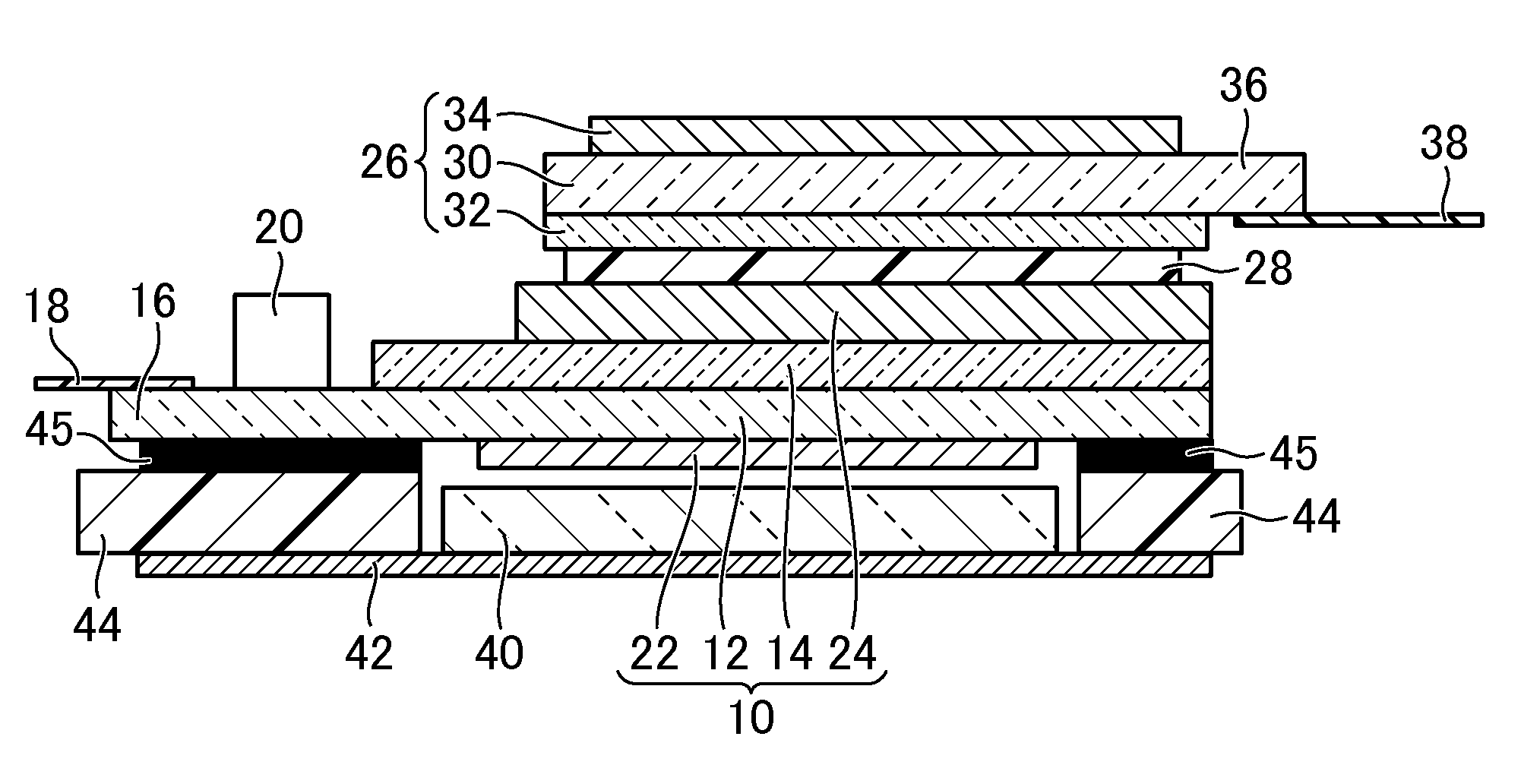
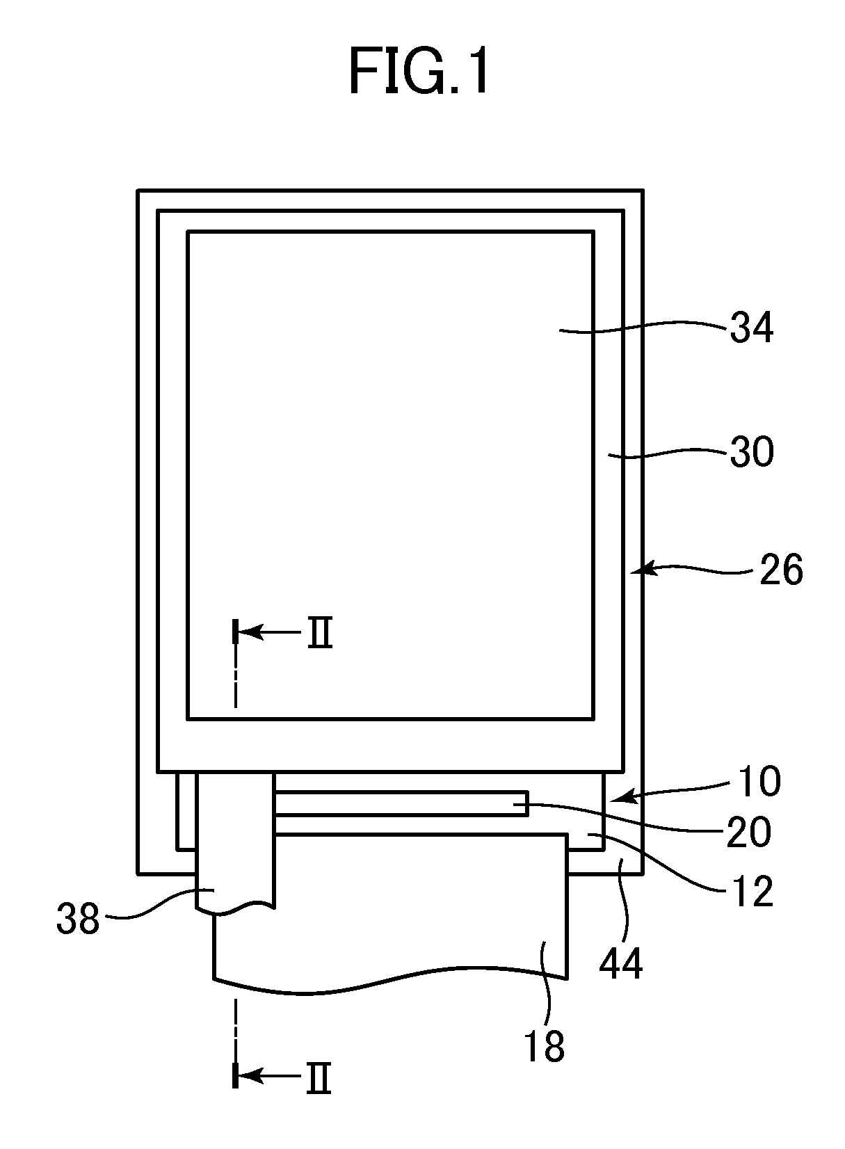
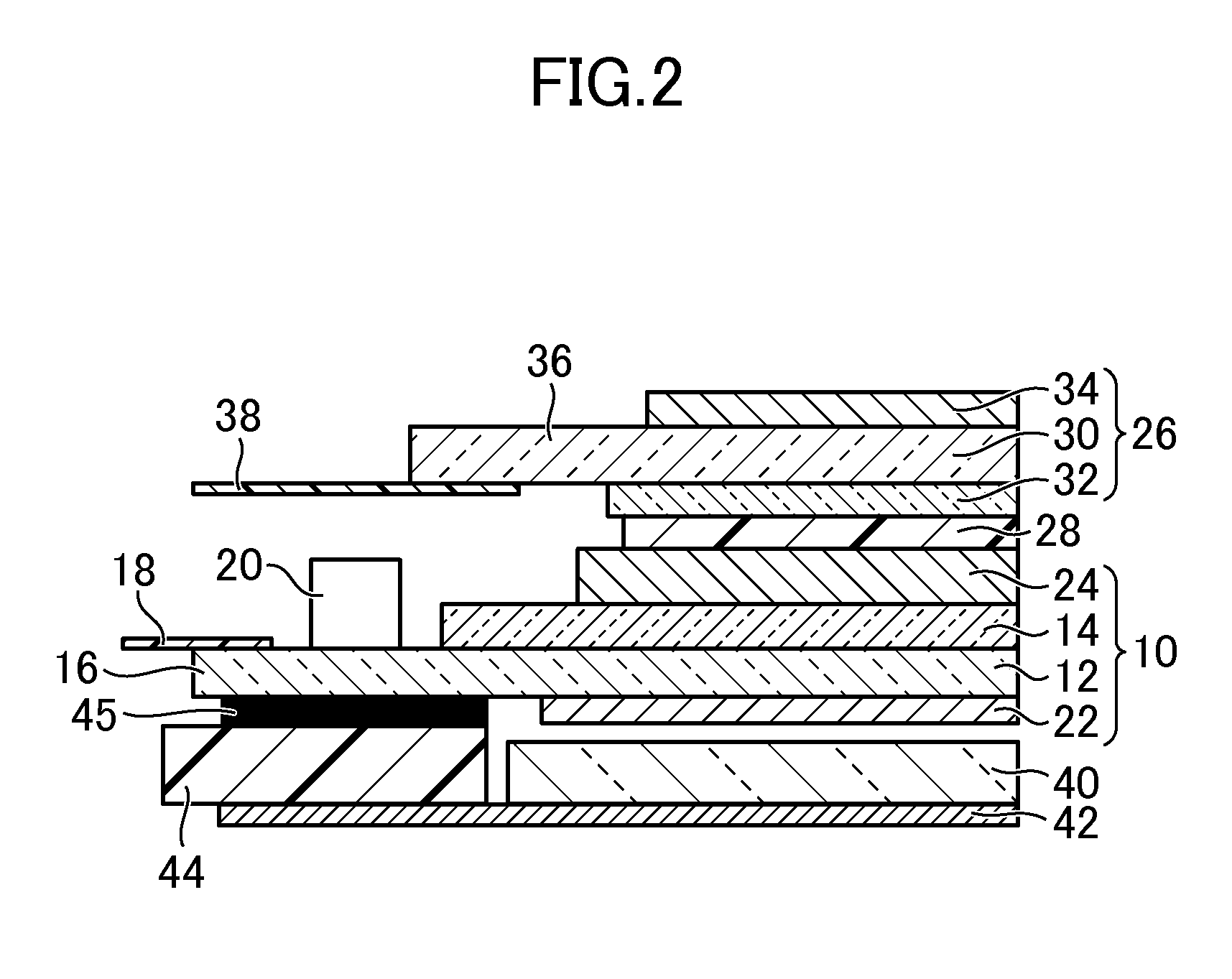
[0018]FIG. 1 is a plan view showing a display device according to an embodiment of the invention. FIG. 2 is a sectional view along II-II line of the display device shown in FIG. 1.

[0019]The display device has a display panel 10. The display panel 10 has a substrate 12 and a substrate 14 opposed to each other. The substrate 12 and the substrate 14 are formed using a transparent material such as glass. In the embodiment, the display panel 10 is a liquid crystal display panel, and liquid crystal (not shown) intervenes between the substrate 12 and the substrate 14. Any system such as the IPS (In Plane Switching) system, the TN (Twisted Nematic) system, or the VA (Vertical Alignment) system may be employed as the driving method of liquid crystal, and electrodes and wires are formed according to the system. Alternatively, the display panel 10 may be an organic EL (Electro Luminescence) panel.

[0020]The substrate 12 is a TFT (Thin Film Transistor) substrate. On the surface of the substrate ...

second embodiment

[0031]FIG. 3 is a sectional view showing a display device according to the second embodiment of the invention.

[0032]In the embodiment, the display panel 10 and the liquid crystal panel 26 are provided so that the projection part 36 of the substrate 30 and the projection part 16 of the substrate 12 may project in opposite directions to each other. According to the embodiment, there is no obstacle above the projection part 16 of the substrate 12 and there is no obstacle below the projection part 36 of the substrate 30. The rest of the structure corresponds to that explained in the first embodiment.

third embodiment

[0033]FIG. 4 is a sectional view showing a display device according to the third embodiment of the invention.

[0034]In the embodiment, the display panel 10 and the liquid crystal panel 26 are provided so that the projection part 36 of the substrate 30 and the projection part 16 of the substrate 12 may project in opposite directions to each other.

[0035]Further, the display device has a housing 46 that houses the display panel 10 and the liquid crystal panel 26. The housing 46 has a part provided around the display panel 10 and the liquid crystal panel 26. The housing 46 includes a lower frame 48 provided at the outer side (lower side) of the frame 44. A cover substrate 50 is provided to face the liquid crystal panel 26, and the cover substrate 50 is held by the housing 46 using a double-sided adhesive tape 52. Note that the cover substrate 50 is formed using a light-transmissive (e.g., transparent) material such as glass, and a light-blocking layer 54 formed by printing is provided in...


PUM

PropertyMeasurementUnit
flexibleaaaaaaaaaa
distanceaaaaaaaaaa
transparentaaaaaaaaaa

Abstract

A display device includes a display panel, a liquid crystal panel superimposed on the display panel for enabling naked-eye stereoscopic view by separating a left-eye image and a right-eye image displayed on the display panel, and a flexible wiring substrate attached to the liquid crystal panel. The liquid crystal panel has a substrate and a substrate opposed to each other. The substrate has a projection part that projects from the substrate. The flexible wiring substrate is attached to a surface of the projection part of the substrate at the substrate side. The substrate is formed to be thinner than the substrate and provided at a side of the display panel.

Description

CROSS-REFERENCE TO RELATED APPLICATION[0001]The present application claims priority from Japanese application JP2012-038513 filed on Feb. 24, 2012, the content of which is hereby incorporated by reference into this application.BACKGROUND OF THE INVENTION[0002]1. Field of the Invention[0003]This invention relates to a display device.[0004]2. Description of the Related Art[0005]Recently, products meeting the requirement of stereoscopic display of images have been developed, and liquid crystal display devices having parallax barrier liquid crystal panels for naked-eye view have been known as small and medium equipment such as cellular phones and portable information terminals (JP 2004-294862 A). The parallax barrier liquid crystal panel is superimposed on a liquid crystal display panel.[0006]Since a flexible wiring substrate is attached to the parallax barrier liquid crystal panel for electrical connection, one of the substrates sandwiching liquid crystal is projected. Thinner parallax...

Claims


Application Information

Patent Timeline
Patent Type & Authority Patents(United States)
IPC IPC(8): G02F1/1337H04N13/04
CPCH04N13/0411H04N13/0409H04N13/31H04N13/312
Inventor OOHIRA, EIJI
Owner JAPAN DISPLAY INC
Why Eureka
Try Eureka