Slide assist mechanism and draw-in unit

a technology of sliding assist mechanism and draw-in unit, which is applied in the direction of wing accessories, furniture parts, manufacturing tools, etc., can solve the problems of easy interference of latches, difficult flat downsizing, and easy damage to sliding properties, so as to improve the stability of the sliding mechanism and reduce the difficulty of sliding. , the effect of preventing oscillating or inclining

Inactive Publication Date: 2014-11-18
NIFCO INC
View PDF24 Cites 8 Cited by
  • Summary
  • Abstract
  • Description
  • Claims
  • Application Information

AI Technical Summary

Benefits of technology

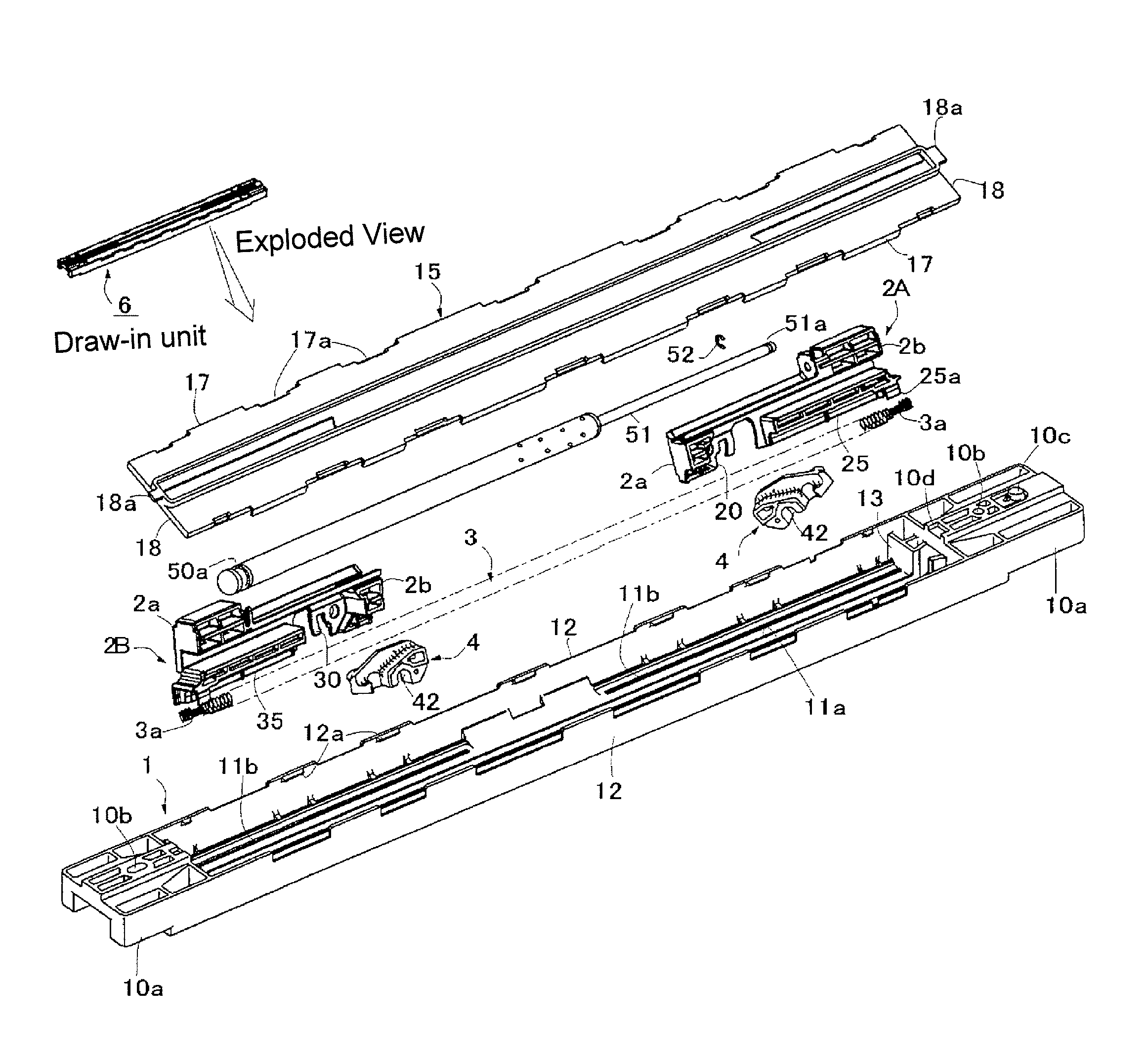
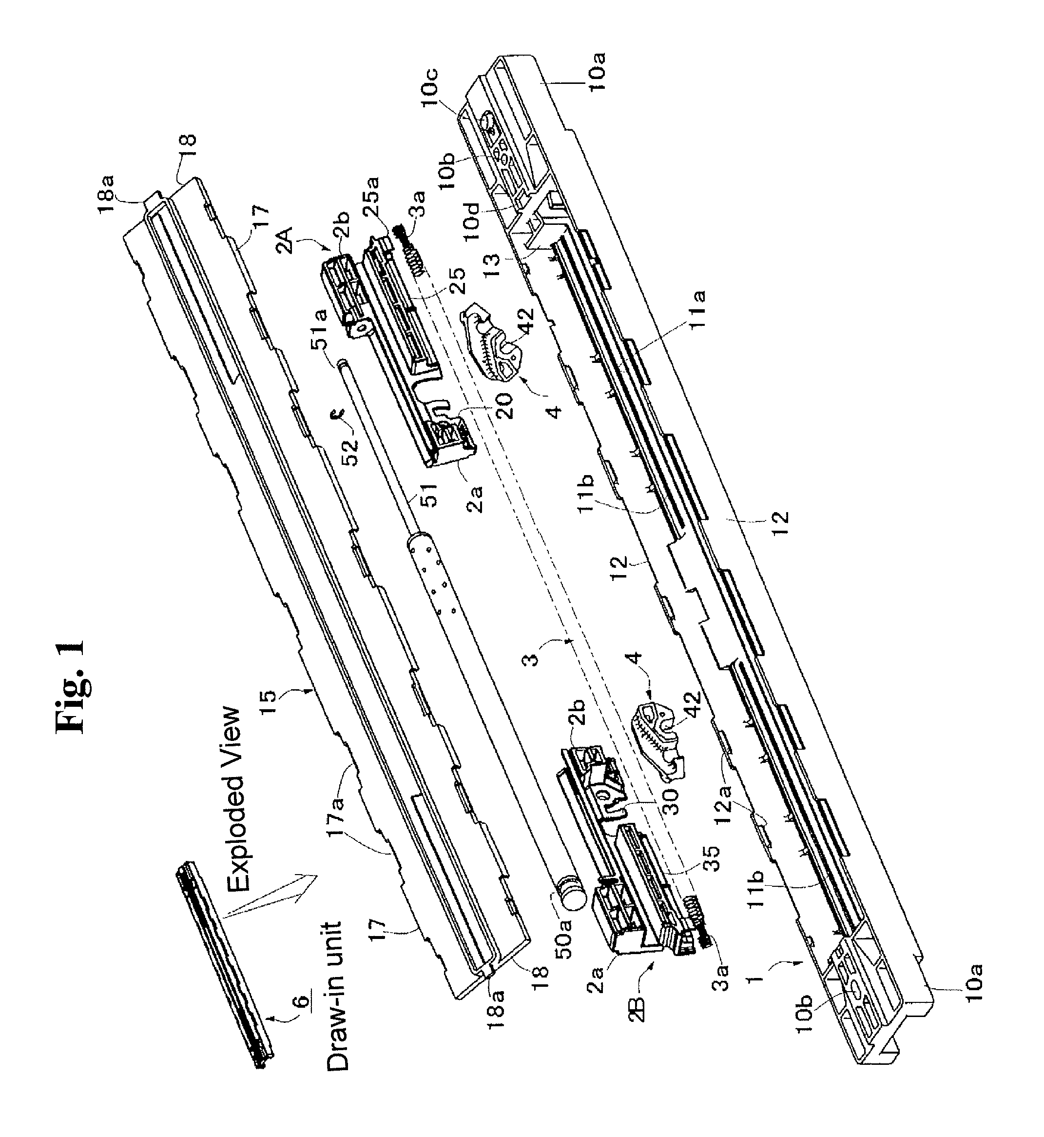
[0019]As for the slide assist mechanism according to the first aspect of the present invention, in the slider, the urging device is disposed on the lower surface side, and one end in the sliding direction includes the attachment device for the urging device, so that even in a case where the coil spring whose entire size is long is used as the urging device, the slide assist mechanism of the present invention allows to easily prevent from buffering with the latch so as to be capable of maintaining the simplification, the flat downsizing, and the excellent operation property.
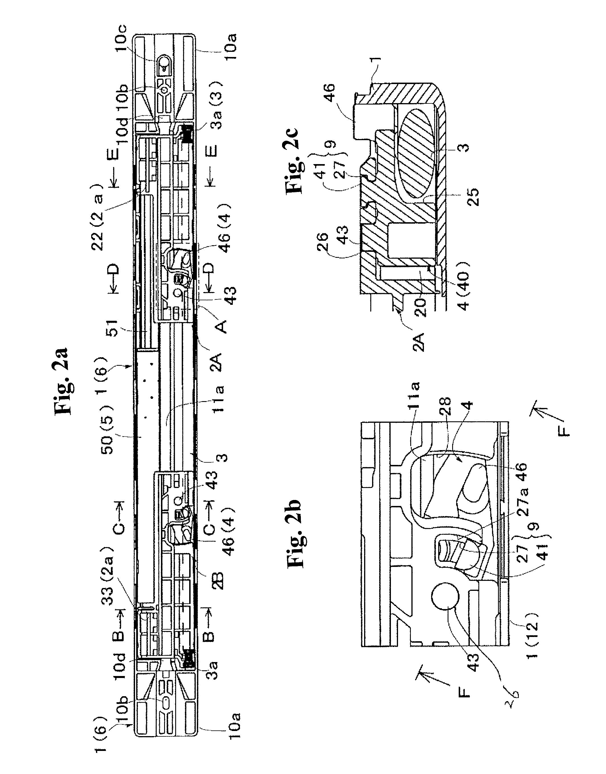
[0020]As for the slide assist mechanism according to the second aspect of the present invention, when the latch is switched between the standby position and the draw-in position through the operation member on a moving body side, due to the control device provided between the latch and the slider, the horizontal rotation relative to the slider is maintained to prevent from oscillating or inclining. Thereby, in the present invention, as in the case of an embodiment, even in a case where the coil spring (the coil spring with a length corresponding to a length between a left end of a left-side slider and a right end of a right-side slider in a state wherein the urging force is released) whose entire size is the longest is used as the urging device, since the control device for the latch is provided between the latch and the slider, even if the guide device (for example, the projection on a lower surface of the latch, and the guide groove on a lower surface of the case) provided between the latch and the lower surface of the case shown, for example, in the Patent Document 1 is omitted, a position switchover of the latch is allowed to be maintained stably and assuredly so as to be capable of improving the operation property.
[0021]The draw-in unit according to the third aspect of the present invention becomes useful in obtaining advantages of the slide assist mechanism.

Problems solved by technology

On the other hand, for example, in a draw-in process, an urging force in an early phase differs substantially from an urging force just before a final phase, and due to that, a sliding property can be easily damaged.
However, if such coil spring is used, the latch can be easily interfered with the coil spring, and also concerning the guide device (a structure fitting the aforementioned up and down projections 52 and 52 in the guide grooves 14 and 19 on the upper and lower surfaces of the case) guiding a position to switchover the latch, the projections and the guide grooves positioned on a coil spring side have to be omitted.
However, in this case, flat downsizing becomes difficult so as to be difficult to be adopted.

Method used


Image

  • Slide assist mechanism and draw-in unit
  • Slide assist mechanism and draw-in unit
  • Slide assist mechanism and draw-in unit

Examples


modified examples

[0062]FIGS. 4(a) and 4(b) show two modified examples, wherein the aforementioned control device 9 (comprising the supporting shaft 41 and the supporting groove 27) is changed, by corresponding them to FIG. 2(c). In the explanation, portions same as those in the aforementioned embodiment are designated by the same reference numerals and only the change will be demonstrated.

[0063]A control device 9A in FIG. 4(a) comprises a collar portion 29 provided around the shaft portion 43 on a latch side; and a level difference 26a provided on the slider side, and fitted in the collar portion 29. The collar portion 29 has a metallic washer shape, and is supported through a locking groove 43a provided around an end of the shaft portion 43. The level difference 26a has a concave shape provided as a center of the shaft hole 26 and receiving the collar portion freely slidably. Then, in the aforementioned structure, the latch 4 is integrally placed relative to a latch placement portion 40 on the slid...


PUM


Abstract

A slide assist mechanism includes a case attached to one of a main body or a moving body; a slider disposed freely slidably in the case; a latch supported by the slider so as to be switched between a standby position which locks in a corresponding portion of the case and a draw-in position which releases the locking; a draw-in unit including an urging device; and an operation member attached to the another of the main body or the moving body and switching the latch from the standby position to the draw-in position, or switching the latch from the draw-in position to the standby position. When the latch is switched from the standby position to the draw-in position, due to an urging force which has been accumulated in the urging device, the slide assist mechanism allows the moving body to move from a first position to a second position on a main body side through the operation member. In the slider, the urging device is disposed on a lower surface side, and also one end in a sliding direction includes an attachment device for the urging device.

Description

RELATED APPLICATIONS[0001]The present application is National Phase of International Application No. PCT / JP2010 / 060789 filed Jun. 24, 2010, and claims priority from Japanese Application No. 2009-149779, filed Jun. 24, 2009.FIELD OF TECHNOLOGY[0002]The present invention relates to a slide assist mechanism which assists an operation switching a moving body from a first position to a second position, or from the second position to the first position on a main body side by using an urging force.BACKGROUND ART[0003]FIGS. 12(a) and 12(b) show a slide assist mechanism of Patent Document 1. In the example, a main body is disposed to freely slide a sliding door; a projection body 9 which is an operation member is provided in the sliding door; and the sliding door is drawn in through the projection body 9 by a draw-in unit which is an essential portion of the slide assist mechanism provided in the main body. The draw-in unit comprises a case 1 attached to the main body; sliders 2A and 2B disp...

Claims


Application Information

Patent Timeline
Patent Type & Authority Patents(United States)
IPC IPC(8): E05F5/00E05F5/02E05F1/16A47B95/02
CPCE05Y2800/73E05F5/003E05Y2800/00E05Y2201/424E05F1/16E05F5/027E05Y2201/412Y10T16/373E05Y2201/10E05Y2800/24E05F13/02
Inventor SATO, MASAKAZU
Owner NIFCO INC
Why Eureka
Try Eureka