Surgical instrument for applying ligating clips

a surgical instrument and clip technology, applied in the field of surgical instruments, can solve problems such as inability to fix, and achieve the effect of improving the accuracy of the surgical instrumen

Active Publication Date: 2014-11-25
AESCULAP AG
View PDF80 Cites 138 Cited by
  • Summary
  • Abstract
  • Description
  • Claims
  • Application Information

AI Technical Summary

Benefits of technology

[0009]It is particularly advantageous for the projection, upon entering the longitudinal slot, to come into abutment against the two juxtaposed portions of the leg. Thus, the projection not only acts to prevent the ligating clip from being unintentionally pushed back, but, at the same time, this projection also assumes the task of guiding the ligating clip.
[0010]This action is further reinforced if, in accordance with a preferred embodiment, the projection, upon entering the longitudinal slot, comes into abutment, in the longitudinal direction of the longitudinal slot, with various points and / or over a continuous area with the two juxtaposed portions of the leg. In this case, the ligating clip is no longer able to move out of the plane defined by the longitudinal slots, as the projection or projections enter the longitudinal slot and prevent any pivotal movement of the ligating clip out of this plane. Such guidance is particularly advantageous if the ligating clip, when being advanced in the clamping jaws, is not guided over the entire length of the legs but, for example, only in the area of the free ends, as is the case with legs which diverge from the bridge portion to the free end.
[0016]It is particularly advantageous for the projection to have at its distal end an end surface extending transversely to the direction of advance of the ligating clip. After the ligating clip has slid past, the end surface positions itself on the rear side of the ligating clip and safely prevents any moving back of the ligating clip.
[0018]The instrument can be used with particular advantage in the case of a ligating clip in which the legs of the ligating clip diverge from the bridge portion to the free ends of the legs, so that the legs abut only at their free ends against the clamping jaws. Such a ligating clip configuration has the advantage, firstly, that the surgeon has a larger opening cross section at his disposal when applying the ligating clip, and, secondly, the ligating clips placed in a row one behind the other in a cartridge of the instrument can thereby be positioned much closer to one another since an overlapping of consecutive ligating clips is thus possible in the area of their legs.

Problems solved by technology

Such fixing is, however, not possible if the applying position is located at a large spacing from the cartridge.

Method used


Image

  • Surgical instrument for applying ligating clips
  • Surgical instrument for applying ligating clips
  • Surgical instrument for applying ligating clips

Examples


Embodiment Construction

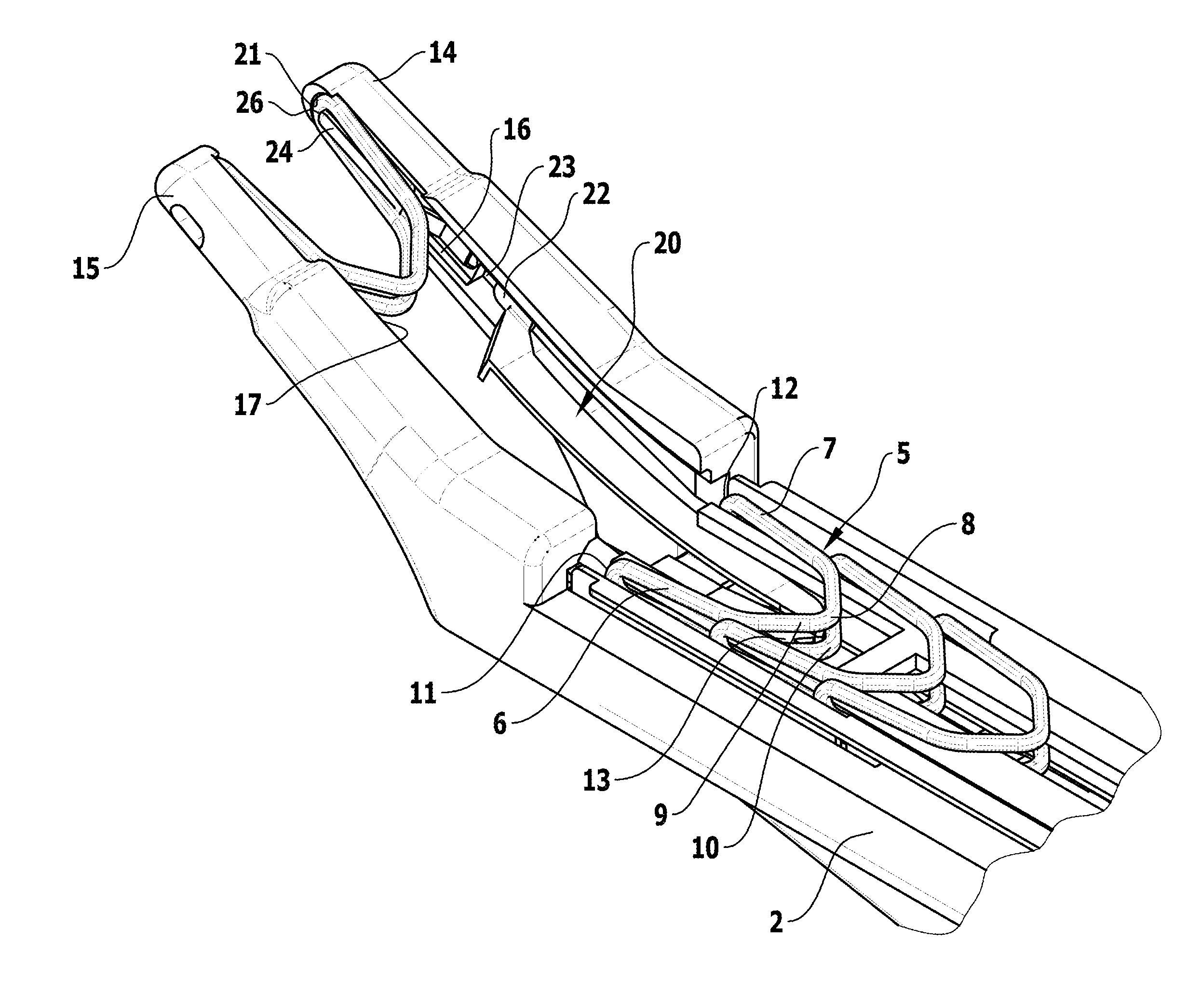
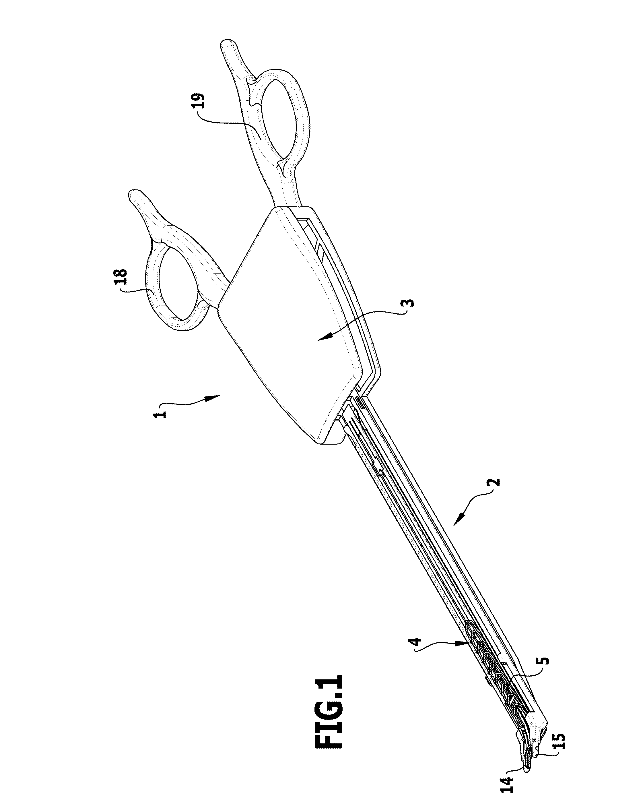
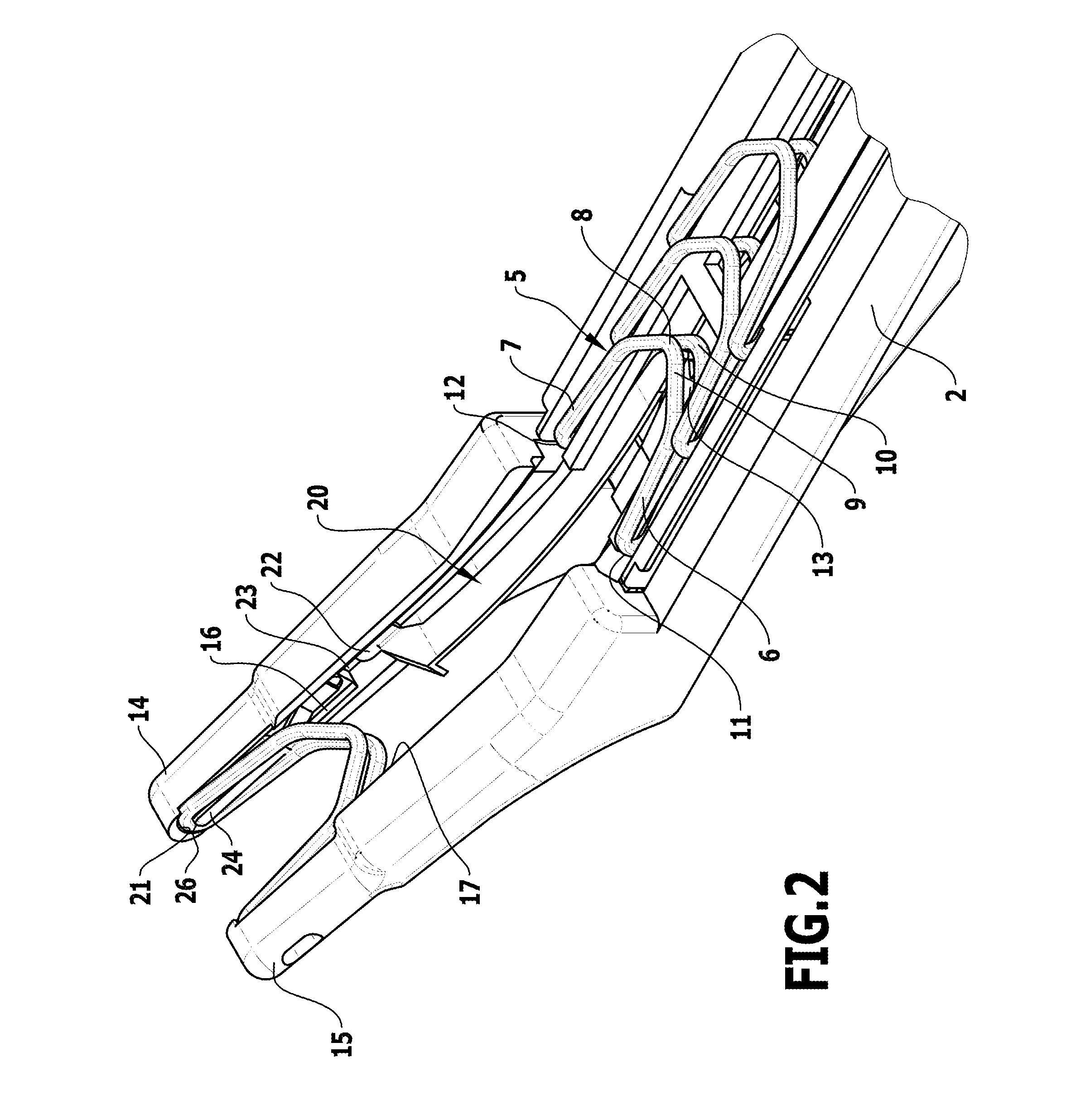
[0027]The surgical instrument 1 shown in the drawings comprises an elongate shaft 2 which at its proximal end opens into a handle part 3. Inserted in the shaft 2 is a cartridge 4 in which a fairly large number of ligating clips 5 are accommodated one behind the other. The ligating clips 5 are of overall C-shaped design with two juxtaposed legs 6, 7 which are joined to each other by a bridge portion 8. The ligating clips 5 consist of two portions 9, 10 extending in a juxtaposed manner over the entire length of the ligating clip, which are joined to each other only at the free ends 11, 12 of the legs 6, 7 and over the remaining length of the ligating clips 5 include a longitudinal slot 13 between them.

[0028]The ligating clips 5 are arranged in such a way in the cartridge 4 that the free ends 11, 12 point in the distal direction, and the legs 6, 7 are constructed so as to diverge slightly in the direction towards the free end, so that the free ends 11, 12 of a ligating clip can be posi...


PUM


Abstract

In a surgical instrument for applying C-shaped ligating clips having two juxtaposed legs which are joined to each other by a bridge portion and are each divided by a longitudinal slot into two juxtaposed portions joined to each other at the free end of the legs, the surgical instrument comprising two juxtaposed clamping jaws with guiding surfaces facing each other for the legs of a ligating clip that lie against the guiding surfaces when the ligating clip is inserted between the clamping jaws, in order to improve the positioning of the ligating clip between the clamping jaws, it is proposed that there be arranged on at least one of the guiding surfaces of the clamping jaws an inwardly protruding projection which, when the ligating clip is advanced along the guiding surfaces, elastically enters the longitudinal slot of the ligating clip.

Description

[0001]The present disclosure relates to the subject matter disclosed in German application number 10 2009 018 821.5 of Apr. 24, 2009, which is incorporated herein by reference in its entirety and for all purposes.BACKGROUND OF THE INVENTION[0002]The invention relates to a surgical instrument for applying C-shaped ligating clips having two juxtaposed legs which are joined to each other by a bridge portion and are each divided by a longitudinal slot into two juxtaposed portions joined to each other at the free end of the legs, the surgical instrument comprising two juxtaposed clamping jaws with guiding surfaces facing each other for the legs of a ligating clip that lie against the guiding surfaces when the ligating clip is inserted between the clamping jaws.[0003]In such surgical instruments, ligating clips are mostly advanced in the distal direction out of a cartridge arranged in a shaft in which they lie in a row one behind the other, and the respective foremost ligating clip is pus...

Claims


Application Information

Patent Timeline
Patent Type & Authority Patents(United States)
IPC IPC(8): A61B17/128A61B17/29
CPCA61B17/1285A61B2017/2911
Inventor SCHULZ, PETERMORALES, PEDROWEISSHAUPT, DIETER
Owner AESCULAP AG
Why Eureka
Try Eureka