Spinal rod and screw securing apparatus and method

a technology of screw securing and rod and screw, which is applied in the field of manipulating and securing bone fixation systems, can solve the problems of many revolutions to achieve reduction, skewed relationship of coupling members relative to each other, and many rotations to achieve reduction. , to achieve the effect of simple stationary grip, simple rod reduction and rotation, and reducing the time of surgery

Active Publication Date: 2014-12-02
XTANT MEDICAL HLDG INC
View PDF96 Cites 33 Cited by
  • Summary
  • Abstract
  • Description
  • Claims
  • Application Information

AI Technical Summary

Benefits of technology

[0011]For these reasons it is desirable to have an improved drive tool apparatus that can be utilized in both minimally invasive and open spinal surgery that provides ease of rod reduction and rotation while decreasing the time of surgery. In addition, the instrument should provide the operator a simple stationary grip to apply anti torque while other instruments within the tool are rotated. The instrument should allow for both the initial and final locking of a cap in a coupling member thus reducing the number of additional instruments necessary to successfully complete a spinal reduction surgery.
[0012]A drive tool apparatus is provided for securing a locking device and a connecting element within a coupling member anchored to a vertebral body. The apparatus has an attachment mechanism for quick engagement to an anchor extension and a single actuating lever that is operable to advance a drive rod, releasably attached to a locking device, linearly along the longitudinal axis of the drive tool. In addition the drive rod of the apparatus is rotatable to initially capture a locking device and connecting element in a coupling member and ultimately fully securing the locking device or cap within the coupling member thus fixing all elements relative to one another. The act of squeezing the lever and advancing the drive rod provides the operator with immediate and constant tactile feedback as to the forces the drive tool is encountering. The stop mechanism insures that the drive rod can only travel in a distal direction, thus the operator need not be concerned with sudden or rapid movement of the drive rod in a proximal direction when releasing the actuating lever. The mechanical guide on the drive tool provides the operator with visual feedback as to the orientation of the locking device and to the depth to which the drive tool has advanced. The mechanical guide thus eliminates the need for the surgeon to determine or guess when the drive rod is fully linearly advanced. The two walls on the mechanical guide give the operator a visual aid during rotation of the drive rod indicating the current status as to whether the locking device is temporarily locked or fully locked. In the fully locked position, the drive rod is no longer mechanically engaged with the drive tool and thus can be easily removed.

Problems solved by technology

When positioning a bone anchor or hook, the orientation of the anatomical structures often results in a skewed relationship of the coupling members relative to each other.
The deformation, or bend, of the spinal connecting member takes the shape of the desired spinal alignment and thus will likely not conform to the skewed relationship of the coupling members.
While these devices may be effective, they are typically complicated, bulky, involve many revolutions to achieve reduction, offer little in the way of tactile feed back to the operator, require two hands for the reduction process, and are not easily adapted to minimally invasive surgery.
Typical instruments that perform rod reduction are not adaptable from open surgery techniques to the limited area afforded in minimally invasive surgery.
In addition the complexity of current instruments, their method of operation, and the need for additional tools to complete the surgery lead to lengthier surgical times.

Method used


Image

  • Spinal rod and screw securing apparatus and method
  • Spinal rod and screw securing apparatus and method
  • Spinal rod and screw securing apparatus and method

Examples


Embodiment Construction

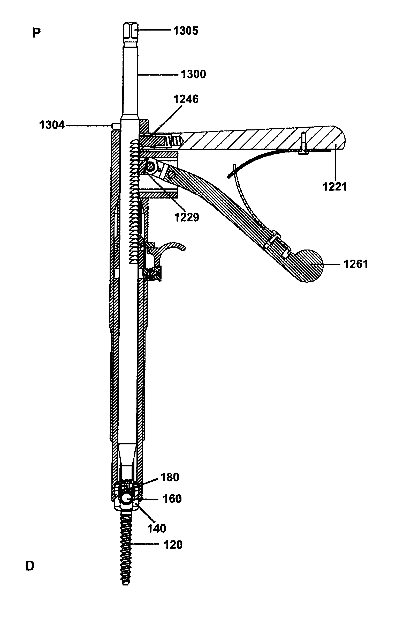
[0056]Prior rod persuader designs typically rely on threaded drive systems, such as in U.S. Pat. No. 7,278,995 to Nichols et al. that are cumbersome and slow because they require multiple rotations of a handle for linearly reducing a spinal rod. The '995 patent requires the surgeon to manipulate two separate handles in order to linearly advance a drive rod and also rotate the drive rod to lock a cap in a coupling member. The use of two handles complicates the tool and the girth of the instrument typically requires the surgeon to occupy both hands in use. The advantage of the improved drive tool apparatus is actuation through a pawl on a unitary drive rod by a mechanical linkage allowing for rapid reduction. The reduction of the drive rod is further expedited in that it can be manually advanced distally through the drive tool while being mechanically restrained from moving in the proximal direction. Manual advancement is undertaken until it is determined that the mechanical advantage...


PUM


Abstract

A minimally invasive and open surgery surgical system for implanting spinal screw assemblies to be connected by a spinal rod is disclosed. In one form, the system includes an improved tool device for inserting a cap insert into an initial and final locking of a screw assembly and securing a spinal rod inserted through an incision to a vertebra. In another form, the system also includes a screw fixation system that allows greater variability in thread diameter for orthopedic implant for in the spine, iliac crest, or bones.

Description

CROSS REFERENCE TO RELATED APPLICATION[0001]This patent claims benefit under 35 U.S.C. §119 (e) to U.S. Provisional Application No. 61 / 304,123 entitled “Spinal Rod and Screw Securing Apparatus and Method” filed Feb. 12, 2010, the contents of which are incorporated herein by reference in its entirety.INCORPORATION BY REFERENCE[0002]U.S. Utility application Ser. No. 11 / 844,259, filed Aug. 23, 2007 and entitled MINIMALLY INVASIVE SURGICAL SYSTEM, is incorporated by reference as if reproduced in its entirety, herein.FIELD OF THE INVENTION[0003]The device disclosed herein provides an instrument for manipulating and securing bone fixation systems for the promotion of proper bone alignment and fusion, in particular, spinal fusion. In the preferred embodiment, the drive tool apparatus is similar to the class of medical instruments generally referred to as rod persuaders, spinal rod reducers and pedicle screw cap inserters, but is not limited to that class of devices.[0004]The invention also...

Claims


Application Information

Patent Timeline
Patent Type & Authority Patents(United States)
IPC IPC(8): A61B17/86A61B17/70
CPCA61B17/7032A61B17/8605A61B17/7086A61B17/864A61B17/8685
Inventor WHITE, JOHNROBINSON, DANIEL RAEHANFELT, MATTHEW F.SANDSTROM, JASON P.HOFFMAN, JEFFREY A.
Owner XTANT MEDICAL HLDG INC
Why Eureka
Try Eureka