
Non-reopening tubing clamp and method of use thereof

a tubing clamp and non-reopening technology, applied in the direction of engine diaphragms, diaphragm valves, mechanical equipment, etc., can solve the problems of affecting the collection/processing procedure, many prior art clamps can be accidentally and/or erroneously opened,

Active Publication Date: 2014-12-09
HAEMONETICS
View PDF6 Cites 0 Cited by
  • Summary
  • Abstract
  • Description
  • Claims
  • Application Information

AI Technical Summary

Benefits of technology

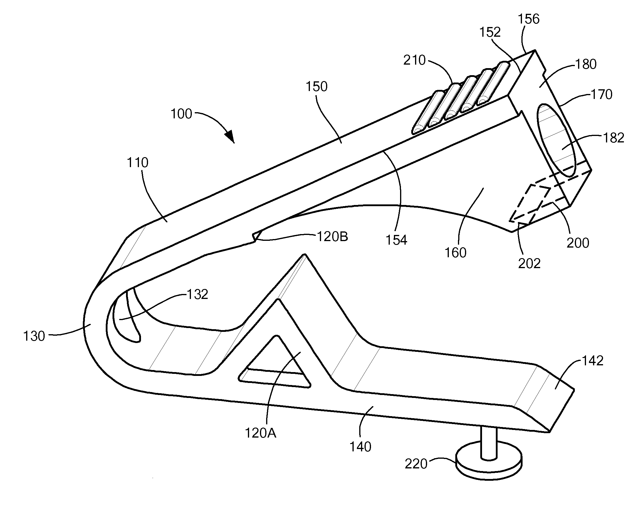
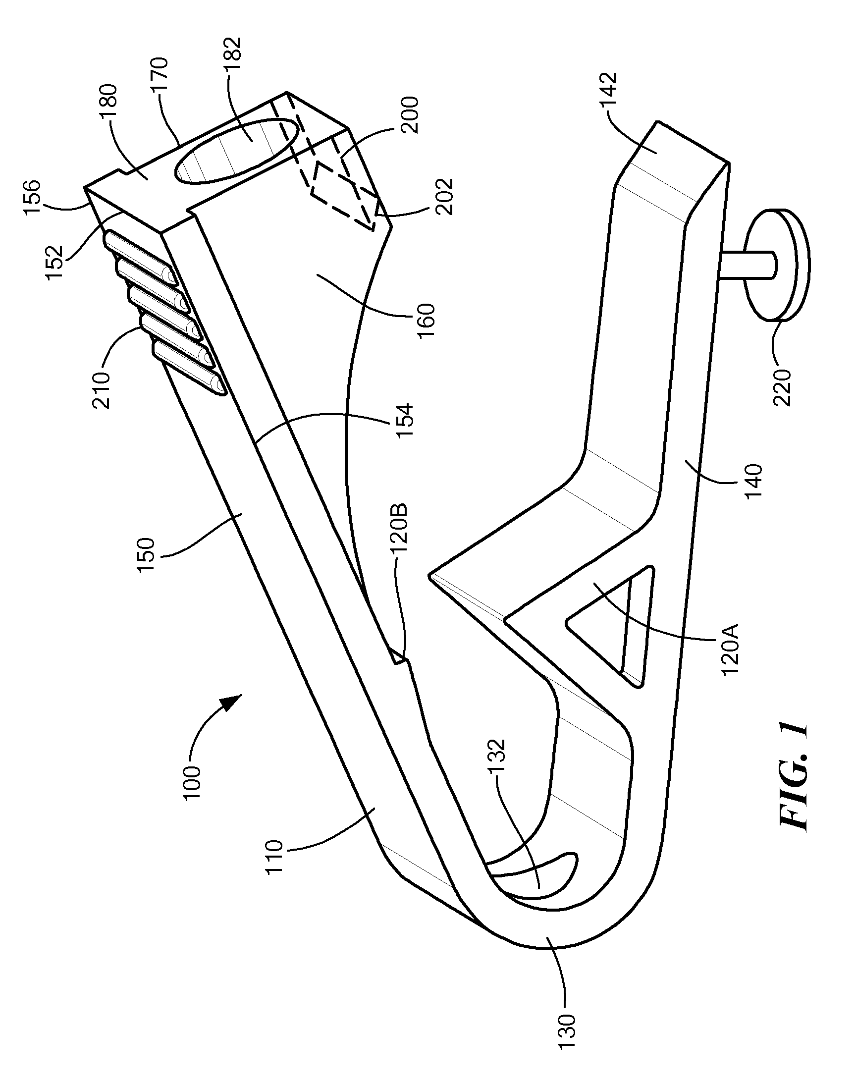
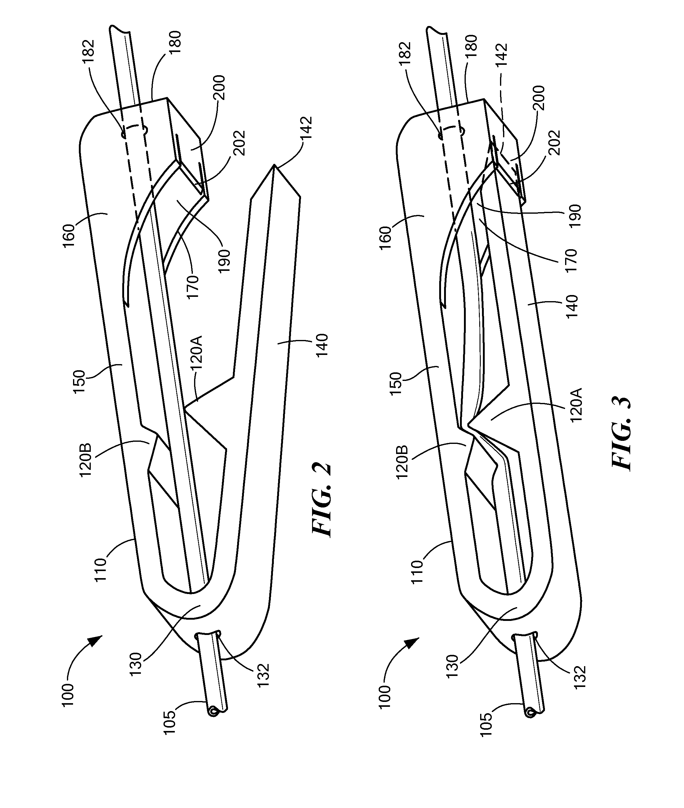
[0004]In a first embodiment of the invention there is provided a medical tubing clamp having a first member, a second member, and a hinge connecting the first and second members to form a body. The second member may have a first and second wall portion that extend distally toward the first member, and a shelf that extends between the first and second wall portions. The first and second wall portions and the shelf may define a recess. The hinge may allow the first and second members to move relative to one another to transition the clamp between an open mode and a closed mode. The first member may be located within the recess and may be supported by the shelf when in the closed mode. The hinge has a first opening for receiving the tubing. The clamp may also have a tubing closure member (on the first or second member) that deforms the tubing to prevent fluid flow through the tubing when in the closed mode.
[0007]In accordance with additional embodiments, a method of controlling fluid flow through a tubing may include providing a tubing clamp having a first member, a second member, and a hinge. The second member may have a first and second wall portion extending distally toward the first member, and a shelf extending between the first and second wall portions. The first and second wall portions, and the shelf may define a recess. The hinge may connect the first and second members to form a body, and may allow the first and second member to move relative to one another to transition the clamp from an open mode to a closed mode. The hinge may also have a first opening configured to receive the tubing. The clamp may also include a tubing closure member that deforms the tubing to prevent fluid flow through the tubing when in the closed position.
[0011]In accordance with further embodiments, a medical tubing clamp includes a first member, a second member, and a hinge. The second member may have a first portion and a reinforced portion extending from the first portion to an end wall, and toward the first member. The end wall may extend below the reinforced portion and may include a shelf extending from a distal end of the end wall. The reinforced portion may have an opening for receiving the tubing. The hinge may connect the first and second members to form a body, and may allow the first and second members to move relative to one another to transition the clamp between an open mode and a closed mode. The first member may be supported by the shelf when in the closed mode. The hinge may include a second opening configured to receive the tubing. The clamp may also include a tubing closure member that deforms the tubing to prevent fluid flow through the tubing when in the closed mode.
[0012]In some embodiments, the clamp may also include a channel located between a bottom surface of the reinforced portion and the shelf. A portion of the first member may be located within the channel when in the closed mode. The reinforced portion may strengthen the end wall to resist deformation along a longitudinal axis of the clamp. The tubing member may be located on the first or second member. The clamp may also include a second tubing closure member that deforms the tubing to prevent fluid flow through the tubing when in the closed position. In such embodiments, the first tubing member may be located on the first member, and the second tubing member may be located on the second member.

Problems solved by technology

However, due to the flexible material used to manufacture them, many prior art clamps can be accidentally and / or erroneously opened by simply deforming a portion of the clamp.
This, in turn, can negatively impact the collection / processing procedure.

Method used


Image

  • Non-reopening tubing clamp and method of use thereof
  • Non-reopening tubing clamp and method of use thereof
  • Non-reopening tubing clamp and method of use thereof

Examples


Embodiment Construction

[0004]In a first embodiment of the invention there is provided a medical tubing clamp having a first member, a second member, and a hinge connecting the first and second members to form a body. The second member may have a first and second wall portion that extend distally toward the first member, and a shelf that extends between the first and second wall portions. The first and second wall portions and the shelf may define a recess. The hinge may allow the first and second members to move relative to one another to transition the clamp between an open mode and a closed mode. The first member may be located within the recess and may be supported by the shelf when in the closed mode. The hinge has a first opening for receiving the tubing. The clamp may also have a tubing closure member (on the first or second member) that deforms the tubing to prevent fluid flow through the tubing when in the closed mode.

[0005]In some embodiments, the second member may include a third wall portion th...


PUM


Abstract

A medical tubing clamp includes a first member, a second member, and a hinge connecting the first and second members to form a body. The second member has a first and second wall portion extending distally toward the first member, and a shelf extending between and connecting the first and second wall portions. The first and second wall portions and the shelf define a recess. The hinge allows the first and second members to move relative to one another to transition the clamp between an open mode and a closed mode. The first member is located within the recess and supported by the shelf when in the closed mode. The hinge has a first opening configured to receive the tubing. The clamp also has a tubing closure member that deforms the tubing to prevent fluid flow through the tubing when in the closed mode.

Description

TECHNICAL FIELD[0001]The present invention relates to tubing clamps, and more particularly to non-reopening tubing clamps that prevent accidental opening of the clamp.BACKGROUND ART[0002]Disposable tubing sets are used in a number of blood collection and blood processing procedures. These tubing sets typically include a variety of collection containers that are connected to one another (and any blood processing equipment) by lengths of flexible tubing. Additionally, some sets also include a venous access device (e.g., a needle) that may be inserted into the patient's arm. At various points during the blood collection and processing one or more of the lengths of tubing may need to be closed off to prevent fluid flow through that section of tubing. To accomplish this, the tubing sets may include clamps located at various points on the tubing. These clamps, when closed, deform the tubing so that fluid is unable to flow past the clamp.[0003]In some instances, it may be necessary to perm...

Claims


Application Information

Patent Timeline
Patent Type & Authority Patents(United States)
IPC IPC(8): A61M5/00F16L21/00
CPCA61M39/286F16L21/007A61M39/284A61M2205/276Y10T24/1418
Inventor PERULLO, JOHN, F.
Owner HAEMONETICS
Learn More