Automatic inoculating system and method for depositing a sample on a substrate in a pattern

a technology of inoculating system and pattern, which is applied in the field of automatic devices for inoculating culture substrates, can solve the problems of delicate maintenance of prior art devices and insufficient reliability of typical prior art devices, and achieve the effect of convenient removal and replacemen

Active Publication Date: 2014-12-09
INTERLAB
View PDF2 Cites 0 Cited by
  • Summary
  • Abstract
  • Description
  • Claims
  • Application Information

AI Technical Summary

Benefits of technology

[0009]The means for raising and lowering the arm can, for example, take the form of a piston that is movable between bottom and top positions. The piston can be disposed near but spaced from the axis of the arm, and the arm can rest atop an upper end of the piston, possibly without being mechanically attached thereto. With that, the arm can freely lift off of the top of the piston, such as when the stylus makes contact with a surface, such as the surface of the substrate.
[0010]The means for retaining the stylus can preferably retain the stylus such that it can be removed from the distal portion of the arm without tools. That can, by way of example, be carried out by a ring fixed to the stylus in combination with a housing retained in the distal portion of the arm where the housing removably receives the ring. The ring can, for example, be fixed, preferably glued, to the stylus. Where the ring is fixed to the stylus, such as by gluing, it is more convenient to remove and replace a given kit of such components to achieve predetermined functionality.

Problems solved by technology

The maintenance of the devices of the prior art is delicate.
In addition, typical prior art devices do not have satisfactory reliability necessary to producing consistent patterns of inoculation.

Method used


Image

  • Automatic inoculating system and method for depositing a sample on a substrate in a pattern
  • Automatic inoculating system and method for depositing a sample on a substrate in a pattern
  • Automatic inoculating system and method for depositing a sample on a substrate in a pattern

Examples


Embodiment Construction

[0028]The system and method disclosed herein are subject to a wide variety of embodiments. However, to ensure that one skilled in the art will be able to understand and, in appropriate cases, practice the present invention, certain preferred embodiments of the broader invention revealed herein are described below and shown in the accompanying drawing figures. Therefore, before any particular embodiment of the invention is explained in detail, it must be made clear that the following details of construction and illustrations of inventive concepts are mere examples of the many possible manifestations of the invention.

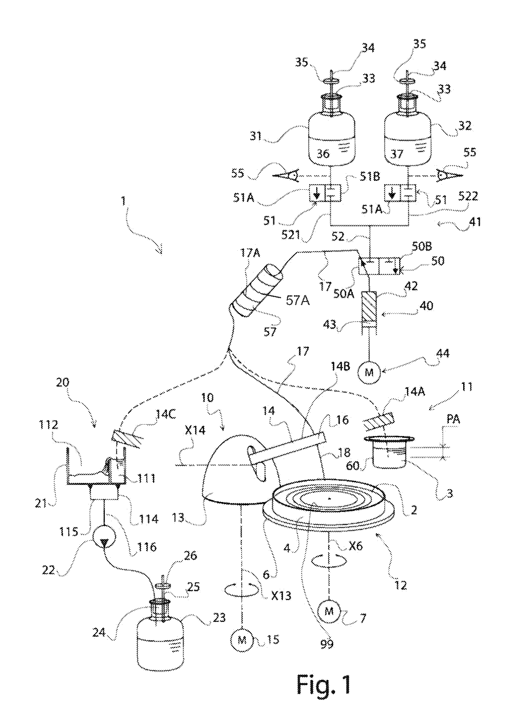
[0029]FIG. 1 illustrates an automatic system 1 according to the invention for inoculating a substrate 2 with a sample 3 to be analyzed. In the illustrated example, the substrate 2 is contained in a Petri dish 4 in the form of a gel, and the sample 3 is substantially liquid.

[0030]The illustrated system 1 includes a supply area 11 for the sample 3 to be tested and an inocul...


PUM

PropertyMeasurementUnit
forceaaaaaaaaaa
gravityaaaaaaaaaa
axis of rotationaaaaaaaaaa

Abstract

An automatic inoculating system for depositing a sample on a substrate in a predetermined pattern. A turret is rotatable about a vertical axis, and an arm retained by the turret is pivotable about a horizontal axis. A stylus retained at a distal portion of the arm sucks up and dispenses the sample, such as by use of a pumping system in fluidic communication with the stylus. A support rotatably retains the substrate. The arm can be raised and lowered, such as by a cylinder on which the arm rests without a retaining mechanical connection therebetween. The arm can thus freely lift off the cylinder as when the stylus contacts the surface of the substrate. The sample can thus be deposited on the substrate in a predetermined pattern by a dispensing from the stylus in combination with rotation of the turret and the substrate and a pivoting of the arm.

Description

FIELD OF THE INVENTION[0001]The present invention relates to the field of automatic devices for inoculating a culture substrate with a sample to be analyzed, usually a substantially liquid sample. It relates more particularly to a system to take and inoculate the sample, for example, on a substrate in a Petri dish.BACKGROUND OF THE INVENTION[0002]In an automatic inoculating device, each sample is taken in a sample tank by the automatic device using a stylus. The sample is then distributed on the substrate surface using the same stylus. Between each inoculation, it is proper to clean the stylus to avoid contamination of the next sample.[0003]In automatic devices of the prior art, the stylus is dipped in several tanks. The first tank may contain a disinfectant, and the following tanks may contain sterile water for rinsing the disinfectant. Such a system and method is described in, for example, U.S. Pat. No. 5,547,872 o Schalkowsky et al.[0004]The stylus is typically moved from one are...

Claims


Application Information

Patent Timeline
Patent Type & Authority Patents(United States)
IPC IPC(8): C12M1/26B01L3/02C12Q1/24B05C5/02
CPCB05C5/02C12M33/04
Inventor JALENQUES, EMMANUEL
Owner INTERLAB
Why Eureka
Try Eureka