
Handheld scan tool with fixed solution capability

a technology of fixed solution and scan tool, which is applied in the direction of vehicle testing, structural/machine measurement, instruments, etc., can solve the problems of a daunting task of sorting and evaluating the available vehicle information, more expensive scan tools would have to be used to retrieve live, and scan tools are relatively expensive diagnostic devices

Active Publication Date: 2014-12-09
INNOVA ELECTRONICS
View PDF127 Cites 36 Cited by
  • Summary
  • Abstract
  • Description
  • Claims
  • Application Information

AI Technical Summary

Problems solved by technology

More expensive scan tools would have to be used to retrieve live data and perform live tests on the automotive system.
Compared to code readers, scan tools are relatively expensive diagnostic devices that have a larger number of features.
However, the live data can amount to several hundred readings which a user may need to scan through in order to receive the problem readings.
Due to the increasing complexity of vehicle electrical systems and components, many of which are made by companies other than the manufacturer and utilize different operating protocols, sorting and evaluating the available vehicle information can be a daunting task.
Aftermarket scan tools face the challenge of being able to access and process information not only from the ECU, but also from various associated electrical devices.
Moreover, given the inter-relatedness of vehicle electrical systems and onboard devices, defects in relation to one onboard electrical device may be reflected in other electrical devices, resulting in multiply digital trouble codes, the ultimate cause of which may be yet another device or circuit that does not directly correspond to any of the digital trouble codes identified in the ECU.
The inherent complexity of such systems is compounded by the number of different makes and models of vehicles that are available, and the changes to those vehicles over the years that they are offered.

Method used


Image

  • Handheld scan tool with fixed solution capability
  • Handheld scan tool with fixed solution capability
  • Handheld scan tool with fixed solution capability

Examples


Embodiment Construction

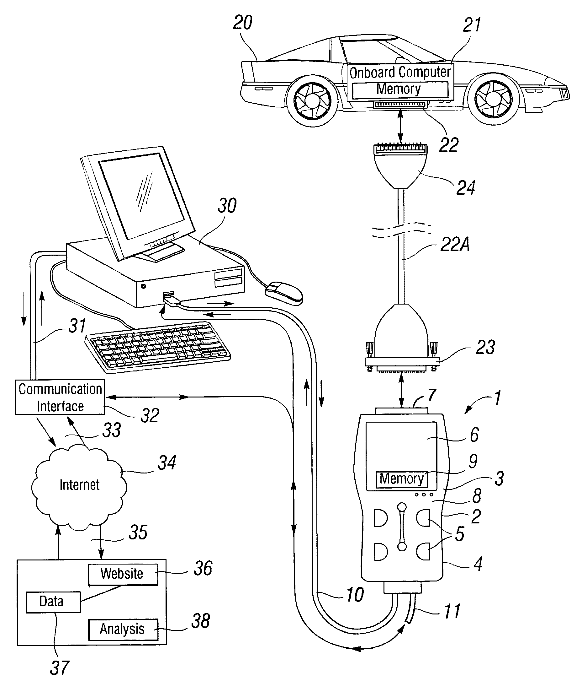
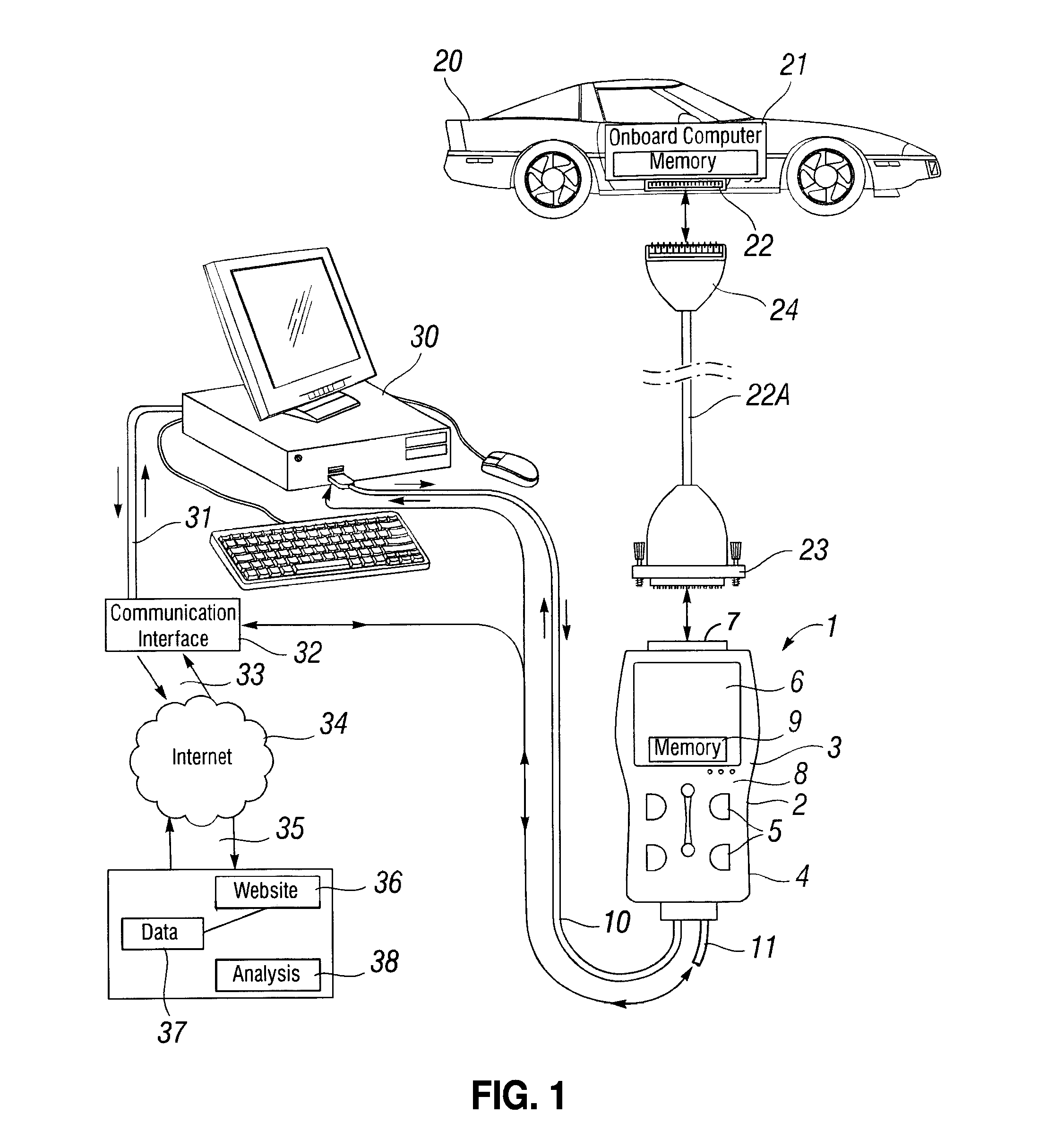
[0035]Referring to FIG. 1, the portable code reader / scanner 1 is comprised of a housing 2 enclosing a hollow interior 3. The exterior 4 of the housing is comprised of a keyboard 5 and a display 6 and a sixteen (16) pin connector 7 at one end.

[0036]The interior 3 of the portable code reader / scanner is comprised of a processor 8 and memory 9 containing information concerning the vehicle, as well as information identifying possible vehicle defect solutions, indexed to the VIN and the DTCs. There also may be a cable connection 10 or a wireless Bluetooth™ connection 11 to a personal desktop or laptop computer 50. The handheld connector 7 interfaces with an automobile 20 onboard computer 21, either directly or with an intervening vehicle interface cable connector 22A having a handheld portable testing device fitting 23 and a car fitting 24.

[0037]In one implementation the personal computer may have a wired or wireless connection 31 to a communication interface 32, which in turn may be conn...


PUM


Abstract

A diagnostic scan tool is provided including a connect / configure module for establishing a communication link between the scan tool and a vehicle electronic control unit (ECU). A vehicle specification module operates to identify a vehicle under test in response to receipt of a vehicle identification number (VIN). A trouble code module receives digital trouble codes (DTCs) from the ECU. A freeze frame data module retrieves freeze frame data from the ECU, the retrieved freeze frame data being functionally associated with a highest priority DTC. A database lists possible vehicle defect solutions, indexed to the VIN and the DTCs. A digital signal processor is operative to derive the highest priority DTC from analysis of the retrieved freeze frame data. The digital signal processor further being operative to regulate selection of a most likely vehicle defect solution associated with the VIN and the highest priority DTC.

Description

CROSS-REFERENCE TO RELATED APPLICATIONS[0001]This application is a continuation-in-part of U.S. patent application Ser. No. 12 / 082,581, filed on Apr. 14, 2008, now abandoned the contents of which are also incorporated herein by reference.STATEMENT RE: FEDERALLY SPONSORED RESEARCH / DEVELOPMENT[0002]Not ApplicableBACKGROUND[0003]The present invention relates generally to vehicle diagnostic systems and methods, and, more particularly, to diagnostic scan tools operative to access diagnostic information from a vehicle electronic control unit (ECU), and to derive a most likely vehicle solution therefrom.[0004]An On-Board Diagnostic, or OBD, system is a computer-based system that was developed by automobile manufacturers to monitor the performance of various components on an automobile's engine, including emission controls. Modern vehicles typically have a vehicle diagnostic system, including one or more modules. Examples of such computer control modules (also known as just “modules”) are: ...

Claims


Application Information

Patent Timeline
Patent Type & Authority Patents(United States)
IPC IPC(8): G06F17/00G07C5/00G07C5/08G01M17/00
CPCG07C5/0808G07C2205/02G06F17/00G07C5/008
Inventor CHEN, IEON C.MADISON, ROBERTANDREASEN, KEITH
Owner INNOVA ELECTRONICS
Learn More