Device and method for forming end of coiled spring

a technology of coil springs and forming apparatuses, which is applied in the direction of mechanical equipment, wound springs, other domestic objects, etc., can solve the problems of complicated structure and difficult shortening time of pigtail forming apparatuses, and achieve the effect of reducing the time from mounting and improving production efficiency

Active Publication Date: 2014-12-23
MITSUBISHI STEEL MFG CO LTD
View PDF8 Cites 1 Cited by
  • Summary
  • Abstract
  • Description
  • Claims
  • Application Information

AI Technical Summary

Benefits of technology

[0015]The present invention has been made to solve the above problems and an object of the present invention is to provide a coil spring end forming apparatus and a coil spring end forming method, which require no engaging structures for regulating movement of a semi-formed spring in the axial direction or in the radius direction and can shorten time from mounting of the semi-formed spring to formation of a pigtail portion.
[0033]As described above, according to the present invention, there are provided a coil spring end forming apparatus and a coil spring end forming method which require no engaging structures for regulating movement of a semi-formed spring in the axial direction or in the radius direction and can reduce the time from mounting of the semi-formed spring to formation of a pigtail portion.

Problems solved by technology

The constitution of the pigtail forming apparatuses is complicated.
It is difficult to shorten time from mounting of the semi-formed spring to formation of the pigtail portion.

Method used


Image

  • Device and method for forming end of coiled spring
  • Device and method for forming end of coiled spring
  • Device and method for forming end of coiled spring

Examples


embodiment 1

1. Embodiment 1

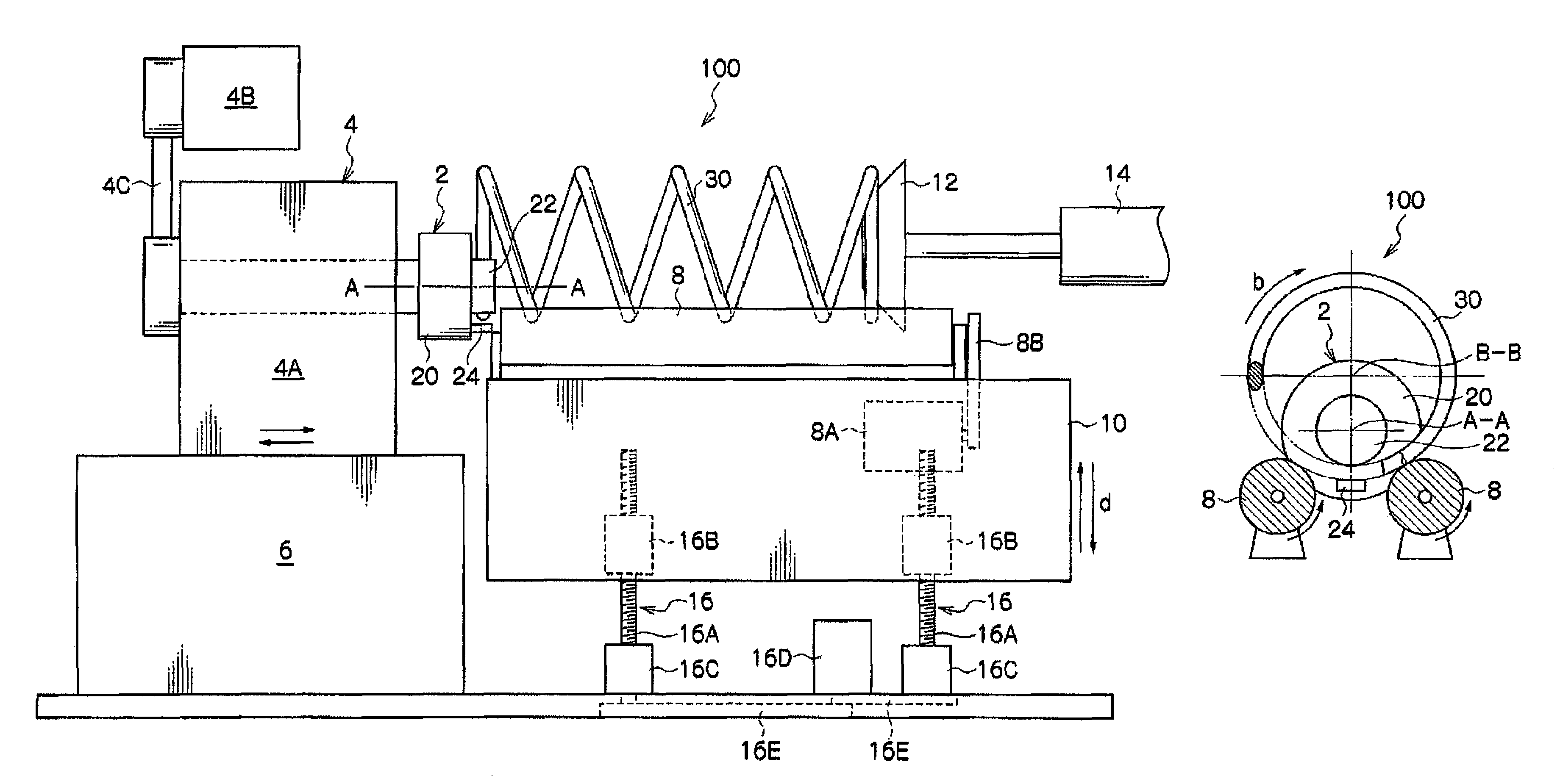
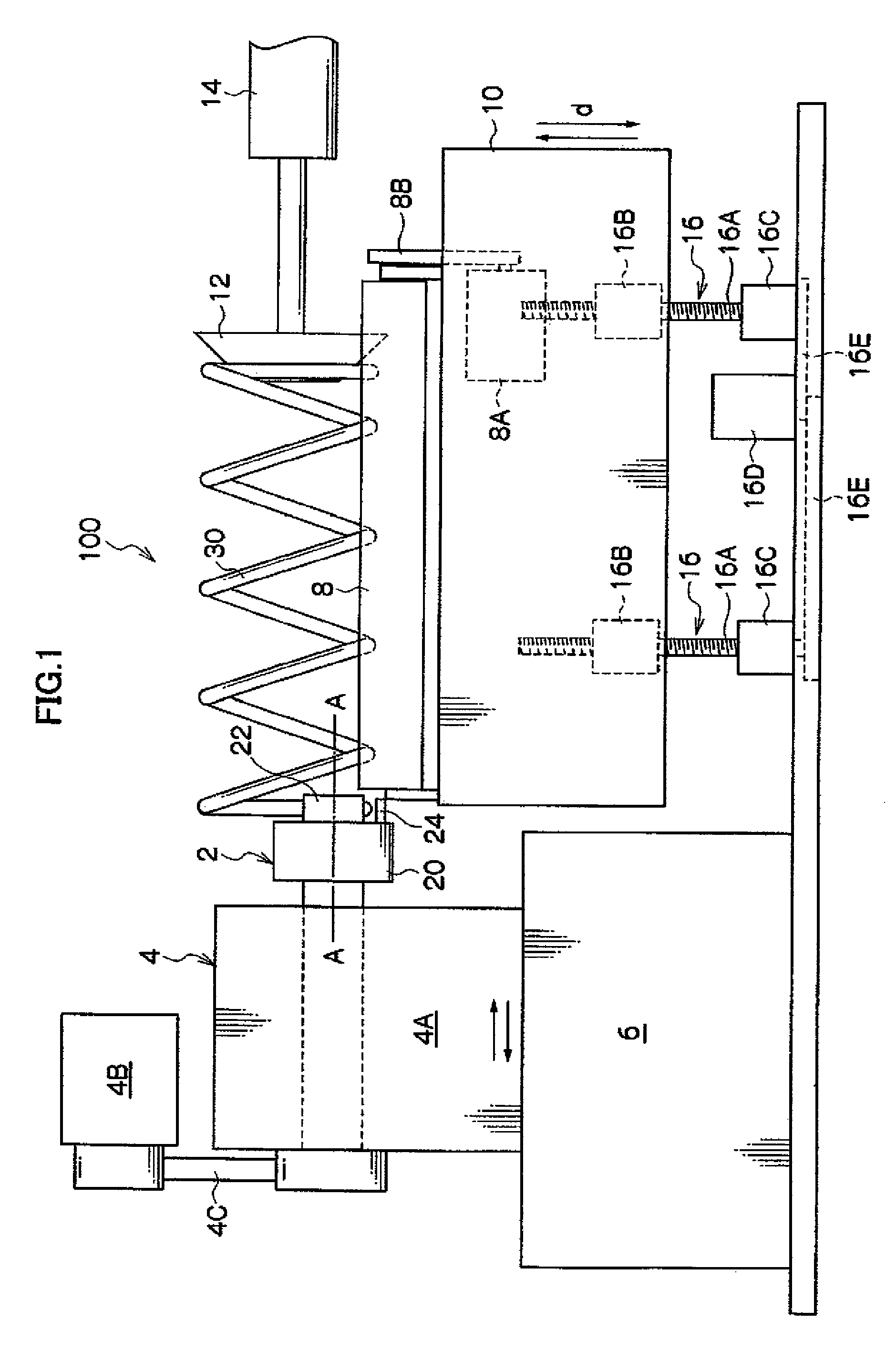
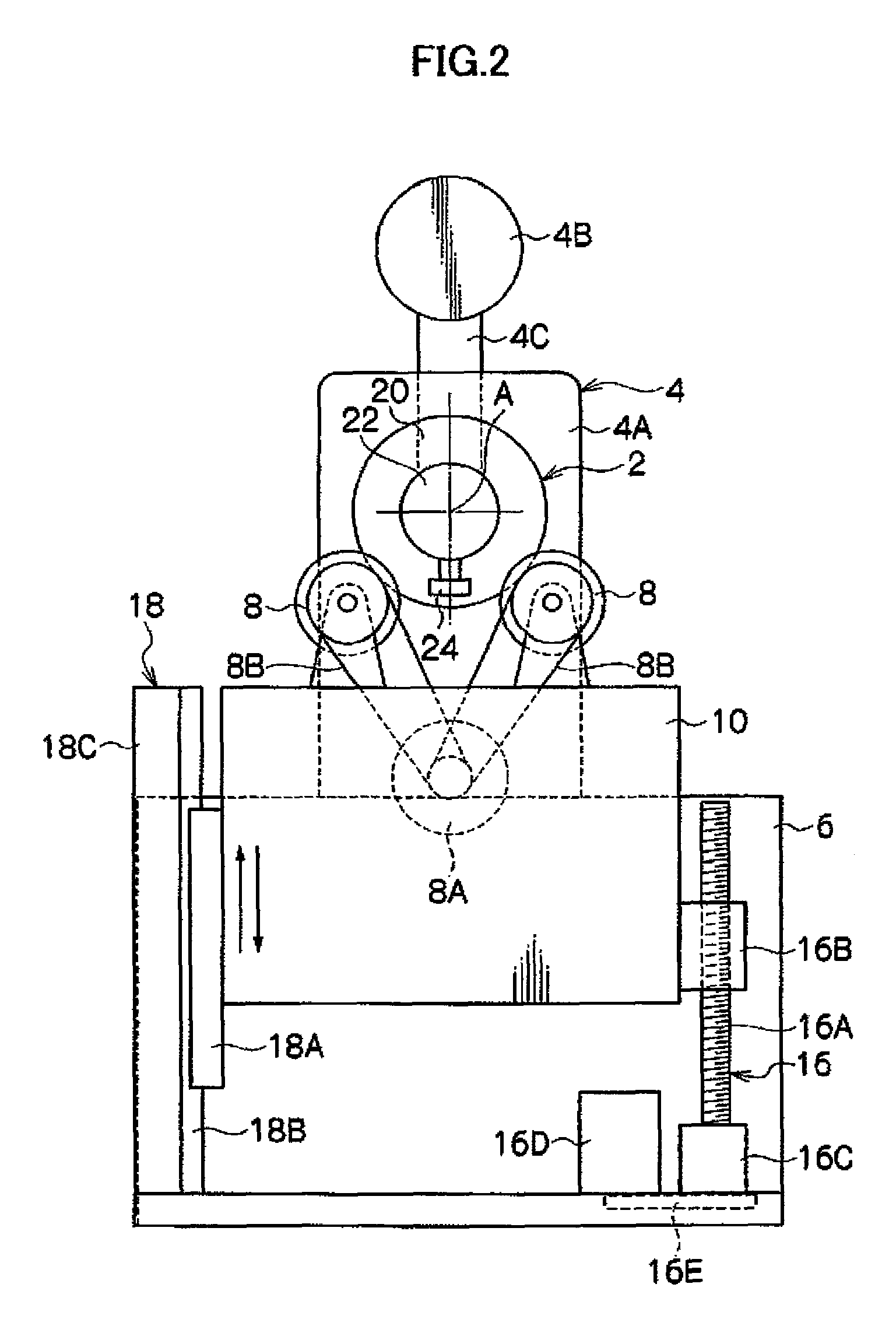
[0048]As shown in FIGS. 1 and 2, a coil spring end forming apparatus 100 according to Embodiment 1 has a clamp portion 2, a rotation driving portion 4 for rotating the clamp portion 2 around an axis A-A, a base 6 for supporting the rotation driving portion 4, a pair of parallel rollers 8 provided adjacent to the rotation driving portion 4 and supported horizontally and in parallel with each other, a platform 10 for supporting the parallel rollers 8 from below, a pusher 12 provided across the parallel rollers 8 and relative to the clamp portion 2, and an actuator 14 fixed above the platform 10 and moving the pusher 12 toward or away from the clamp portion 2.

[0049]As indicated by arrows d, the platform 10 is supported by the base 6 so as to be moved up or down. The base 6 has a ball screw mechanism 16 for moving the platform 10 up or down, and a vertical guide mechanism 18 for supporting the platform 10 for up or down movement and vertically guiding it. The ball screw m...


PUM

PropertyMeasurementUnit
timeaaaaaaaaaa
sliding resistanceaaaaaaaaaa
diameteraaaaaaaaaa

Abstract

A coil spring end forming apparatus is provided that includes a pair of horizontally disposed parallel rollers 8; a mandrel 22; a stopper 20 that is provided adjacent to the circumferential surface of the mandrel 22 and is moved up or down and rotated integrally with the mandrel 22; a clamp jig 24 that is provided so as to be movable toward or away from the mandrel 22 and that holds a semi-formed spring 30 in cooperation with the mandrel 22, and a pusher 12 for pushing the semi-formed spring 30 toward the stopper 20, wherein in a state in which the axis of the mandrel 22 is positioned between the axes of the parallel rollers 8 and the semi-formed spring 30, a clamp portion 2 holds the semi-formed spring 30 at the inner side of a triangle formed by the axes of the parallel rollers 8 and the semi-formed spring 30 and rotates around the axis along the winding direction of the semi-formed spring 30 to form a pigtail portion at one end of the semi-formed spring 30, and a coil spring end forming method is further provided.

Description

[0001]This application is the U.S. National Phase under 35 U.S.C. §371 of Inter national Application PCT / JP2007 / 060645, filed May 24, 2007, which claims priority to Japanese Patent Application No. 2006-149296, filed on 30 May 2006. The International Application was published under PCT Article 21(2) in a language other than English.BACKGROUND OF THE PRESENT INVENTION[0002]1. Field of the Present Invention[0003]The present invention relates to a coil spring end forming apparatus and a coil spring end forming method. More specifically, the present invention relates to a coil spring end forming apparatus and a coil spring end forming method for forming a pigtail portion at the end of a coil spring.[0004]2. Description of the Related Art[0005]In a suspension device of an automobile, a combination of a coil spring as a spring device and a shock absorber inserted into the inner side coil spring is widely used. In such suspension device, a direction of an input from a tire is not always mat...

Claims


Application Information

Patent Timeline
Patent Type & Authority Patents(United States)
IPC IPC(8): B21F3/10B21F3/04B21F35/02F16F1/12B21D11/14
CPCF16F1/12B21F3/04F16F2226/00B21F3/10B21F35/02B21F3/02
Inventor ETO, TAKASHI
Owner MITSUBISHI STEEL MFG CO LTD
Why Eureka
Try Eureka