Supercharge Your Innovation With Domain-Expert AI Agents!

T-step hull form for monohull planing vessels

a hull form and monohull technology, applied in vessel construction, special-purpose vessels, transportation and packaging, etc., can solve the problems of increasing difficult to trim the vessel, and high speed maneuvering of stepped hull vessels, so as to improve the handling and maneuverability characteristics, and the longitudinal surface area of the hull form is increased.

Active Publication Date: 2014-12-23
BRUNSWICK CORPORATION
View PDF10 Cites 5 Cited by
  • Summary
  • Abstract
  • Description
  • Claims
  • Application Information

AI Technical Summary

Benefits of technology

The present invention is a new hull design for monohull planing vessels that improves speed and maneuvering capabilities, particularly during high-speed tracking and turning. It includes a skeg that extends from the step to the transom, which increases the longitudinal surface area of the hull form. This design provides the benefits of a stepped hull while also improving lateral stability and overall handling. The width of the skeg can be adjusted to achieve better stability and handling.

Problems solved by technology

Despite the speed benefits, conventional stepped hull designs are known to reduce stability, particularly at high speeds.
This is because lift is spread laterally across more than one surface, which increases longitudinal stability, making it more difficult to trim the vessel.
Consequently, high speed maneuvering of stepped hull vessels can be quite dangerous, particularly for less-experiences boaters who are not proficient in setting the trim of the vessel.
Further still, conventional stepped hull designs suffer from increased drag at low speeds, before higher speeds cause water to break cleanly off the step
Several attempts at providing stepped hull designs are relatively well-known in the art; however, none are specifically designed to improve handling and stability characteristics, particularly during high speed maneuvering:
As with traditional stepped hull designs, the keel of the hull is stepped as well, decreasing handling stability at high speeds.
Further, the keel is stepped along with the stepped section, limiting high speed handling stability.

Method used


Image

  • T-step hull form for monohull planing vessels
  • T-step hull form for monohull planing vessels
  • T-step hull form for monohull planing vessels

Examples


Embodiment Construction

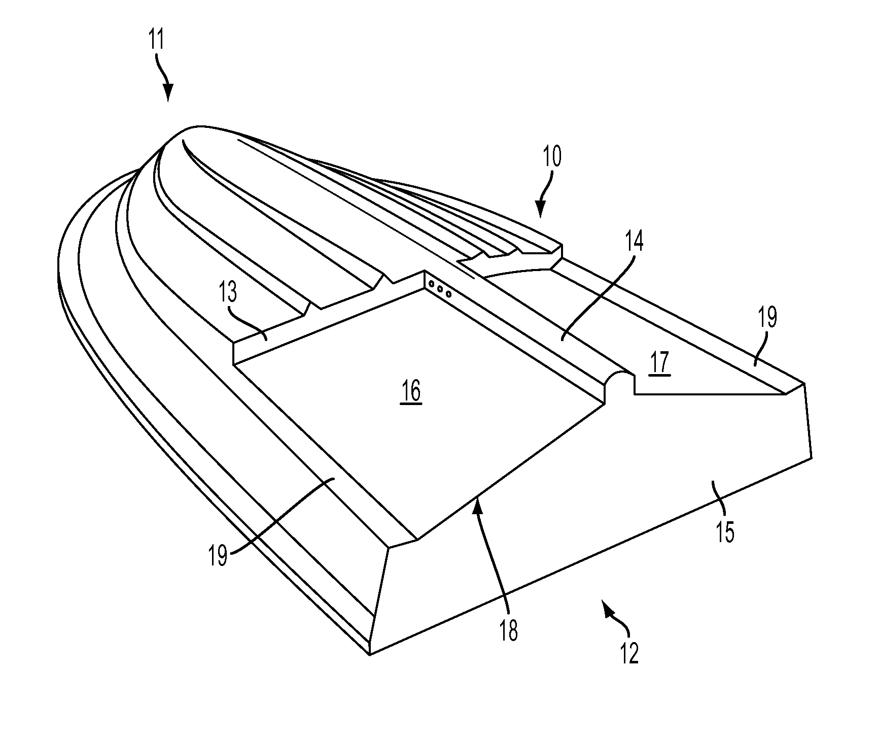
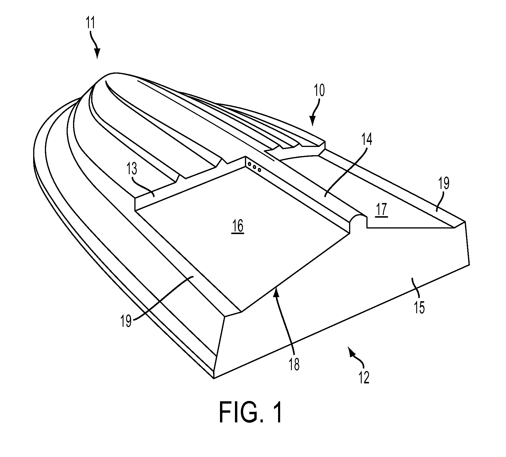
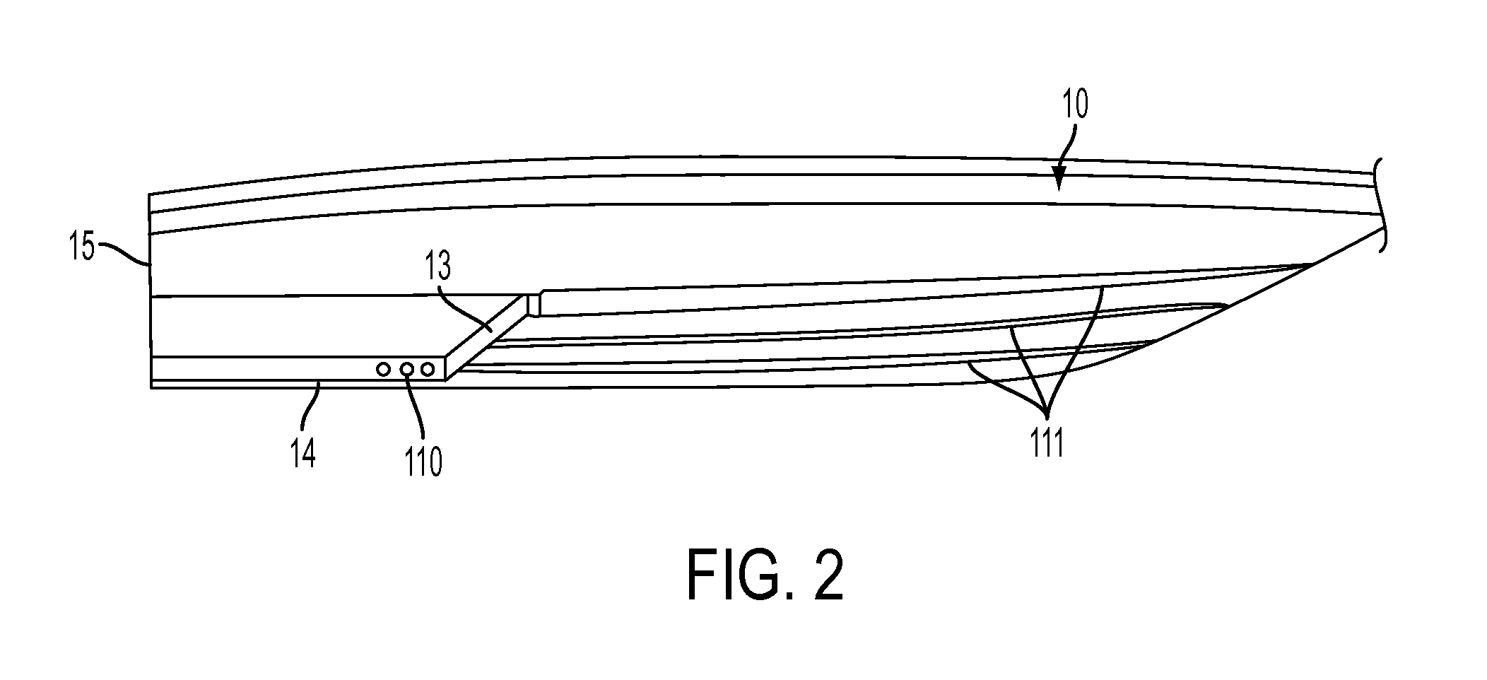
[0027]With reference to FIG. 1, a perspective view of one embodiment of the t-step hullform is shown. As shown, hull form 10 is configured as substantially v-shaped monohull having a forward section 11 and an aft section 12 separated by step 13. Step 13 is oriented substantially transverse with respect to hull form 10. Skeg 14 extends along the length of the hull form 10, from step 13 rearwardly to the transom 15, dividing aft section 12 into a starboard tunnel portion 16 and a port tunnel portion 17. Accordingly, with skeg 14 integrated into and extending substantially perpendicular from step 13, a T-shaped step, or “T-step” hull form is defined. In some embodiments, starboard tunnel portion 16 and port tunnel portion 17 are both ventilated at their respective outboard sides as well as rearward at the transom 15. Starboard tunnel portion 16 and port tunnel portion 17 extend to the chine 18 of hull form 10, and, in some embodiments, the outboard boundary 19 of both portions have a f...


PUM


Abstract

A T-step hull form for monohull planing vessels includes a forward section, an aft section, a transom, a step, and a skeg. The step is transversely oriented and separates the forward section from the aft section, and the skeg extends longitudinally along the length of the hull form from the step rearwardly to the transom, dividing the aft section into a starboard tunnel portion and a port tunnel portion. The starboard and port tunnel portions are ventilated at their respective outboard sides, at the transom, or both. Vents may pass transversely through the skeg. Tunnel flaps may be disposed in each of the tunnel portions and are hingeably attached at the step to allow for adjustability of the step's geometry. The addition of the skeg, which extends from the step to the transom, provides additional longitudinal surface area for the hull form, and in turn increases lateral stability.

Description

CROSS REFERENCE TO RELATED APPLICATIONS[0001]N / ASTATEMENT REGARDING FEDERALLY SPONSORED RESEARCH OR DEVELOPMENT[0002]N / ABACKGROUND OF THE INVENTION[0003]1. Field of the Invention[0004]The present invention generally relates to vessel hulls and more specifically to a T-step hull form for mono-hull planing vessels.[0005]2. Description of Related Art[0006]Conventional stepped hulls are relatively well-known in the art of planing vessel hull forms and are useful in mono-hull designs (as compared to catamaran or trimaran designs). These hulls include one or more steps, or “breaks” in the hull, which are intended to reduce the amount of hull surface that comes in contact with the water. By reducing water contact, friction resistance is reduced leading to faster overall speed capability for a given vessel. Conventional stepped hull designs include a step that runs across the entire width (or “beam”) of the vessel, which step is usually located toward the back half of the hull. The step res...

Claims


Application Information

Patent Timeline
IPC IPC(8): B63B1/32
CPCB63B1/32Y02T70/12B63B1/20B63B2001/202
Inventor HERRINGTON, FREDERICK CHARLESHOTARY, MARK GEORGELEWIS, GEORGE BENJAMIN
Owner BRUNSWICK CORPORATION
Features
  • R&D
  • Intellectual Property
  • Life Sciences
  • Materials
  • Tech Scout
  • Unparalleled Data Quality
  • Higher Quality Content
  • 60% Fewer Hallucinations
Learn More