
Measuring thrombin activity in whole blood

a thrombin activity and whole blood technology, applied in the direction of biochemistry instruments and processes, material testing goods, instruments, etc., can solve the problems of insufficient or inadequate practicality, extreme impreciseness, and strong limitations in the practical use of the techniqu

Active Publication Date: 2014-12-23
SYNAPSE INC
View PDF3 Cites 13 Cited by
  • Summary
  • Abstract
  • Description
  • Claims
  • Application Information

AI Technical Summary

Benefits of technology

[0045]A particular advantage of the invention is that the method enables measurement of thrombin generation in a sample, especially in a whole blood sample which is not diluted or which is minimally diluted, within a range of maximum ten times, especially less or equal to 4 times.
[0046]In a particular embodiment of the described method, the thickness of the layer of sample to be analysed, especially of whole blood is from 1 to 3 mm, especially about 2 mm or less.
[0047]In a particular embodiment of the method, the surface of the sample, especially of the whole blood sample, when it is filled in the wells of the microplate or any appropriate container or support, is larger than 20 mm2 for example from 30 mm2 to 200 mm2, especially larger than 100 mm2, in particular within a range of 150 to 200 mm2
[0048]As an example, the sample is filled in wells of microplates, each well having a diameter of 15 mm and the thickness of the blood sample is less than 2 mm, enabling measurement on a surface of about 175 mm2.
[0049]The measurement of thrombin activity is performed in a way that enables multiple lecture points of the fluorescence at the surface of each sample.
[0050]According to an embodiment of the invention, the method is carried out with a sample, especially a whole blood sample which is filled in the wells of a plate or other container or support wherein said wells also contain a grid especially with a mesh size of 50 μm.

Problems solved by technology

Solutions to this problem have essentially not changed until the 1990ies, offering means that were either practical but inadequate or adequate but impractical.
For the bleeding time it can be said that it is extremely imprecise having a coefficient of variation around 40%, which strongly limits its practical use (34).
Removal of fibrinogen has however the disadvantage of removing an important reactant and cannot be carried out without removing cellular elements such as the important blood platelets.
The use of a fluorogenic substrate introduces two important disadvantages however: 1) fluorescence intensity is not proportional to the concentration of the fluorophore because of the so-called inner filter effect; 2) with the available substates the rate of product formation is not necessarily proportional to the enzyme concentration.
Such substrates at the moment are not available.
The chromogenic method can obviously not be used with whole blood because blood is not translucent.
In short, the method described does not yield reproducible and quantifiable results.
This approach cannot however be thought to represent the physiological situation for two reasons.
Hence the problem remains of how to obtain a signal from which the changing thrombin concentration can be determined in a sample of clotting blood that is less than ten times diluted.
It follows therefrom that the volume from which fluorescence is obtained changes during the reaction and that the geometric form of the surface changes, causing erratic focussing and reflection of light that disturbs the signal recovered.

Method used


Image

  • Measuring thrombin activity in whole blood
  • Measuring thrombin activity in whole blood
  • Measuring thrombin activity in whole blood

Examples


example 1

Multiple Lecture Points, Adding a Mesh and a Cover

[0123]Thrombin generation was triggered as indicated above in three wells. Per well 24 spots were illuminated and measured one after the other. The signals from the 24 points at each reading were added. The results are shown in FIG. 7. It is seen that the signal is augmented and stabilized by adding a grid, here a nylon filter with a 600 μM mesh opening, 51% open area and a thickness of 445 μM (Spectrum Laboratories Inc. Rancho Dominguez Calif., USA). However, the signal spuriously increases with time due to evaporation and concentration of the top layer. This is prevented by covering with a plastic foil. (Thermosprint optical clean sealing tape for QPCR (Bilatec AG, Mannheim, Germany).

example 2

Multiple Lecture Points, Adding a Gel and a Cover

[0124]Thrombin generation was triggered as indicated above in three wells. Per well 24 spots were illuminated and measured one after the other. The signals from the 24 points at each reading were added. To two wells 700 μL of a 50% (v / v) Spehadex-25 in 150 mM NaCl solution is added and the powder is allowed to settle for 5 minutes. The supernatant (300-400 μL) is removed from the well with a pipette.

[0125]Then 120 μL of the clotting blood mixture is added. On top of one of these two wells a plastic foil. (Thermosprint optical clean sealing tape for QPCR (Bilatec AG, Mannheim, Germany) was applied. The results are comparable to those in FIG. 7

example 3

The Light with an Optical Device

[0126]For this experiment one well, with grid and cover as in example 1, was measured with the aid of a Fluostar optima fluorimeter (BMG Labtech, Offenburg, Germany). The light from the sample was collected into a Huygens eyepiece (10× magnification) and read after passing through this optical device. The results are shown in FIG. 8


PUM

PropertyMeasurementUnit
diameteraaaaaaaaaa
sizeaaaaaaaaaa
thicknessaaaaaaaaaa

Abstract

The invention relates to a method for in vitro determining thrombin activity in a sample wherein the sample is a blood sample and thrombin generation is measured by the steps of: —contacting a layer of said sample with a fluorogenic substrate of thrombin, wherein said layer has a thickness within a range of 0.05 to 5 mm and a surface within a range of 10 to 500 mm2; —allowing thrombin to generate in said sample; —measuring the fluorescence emitted from the surface of the layer, by the fluorescent group released from the fluorogenic substrate as a result of enzymatic action of generated thrombin on said fluorogenic substrate.

Description

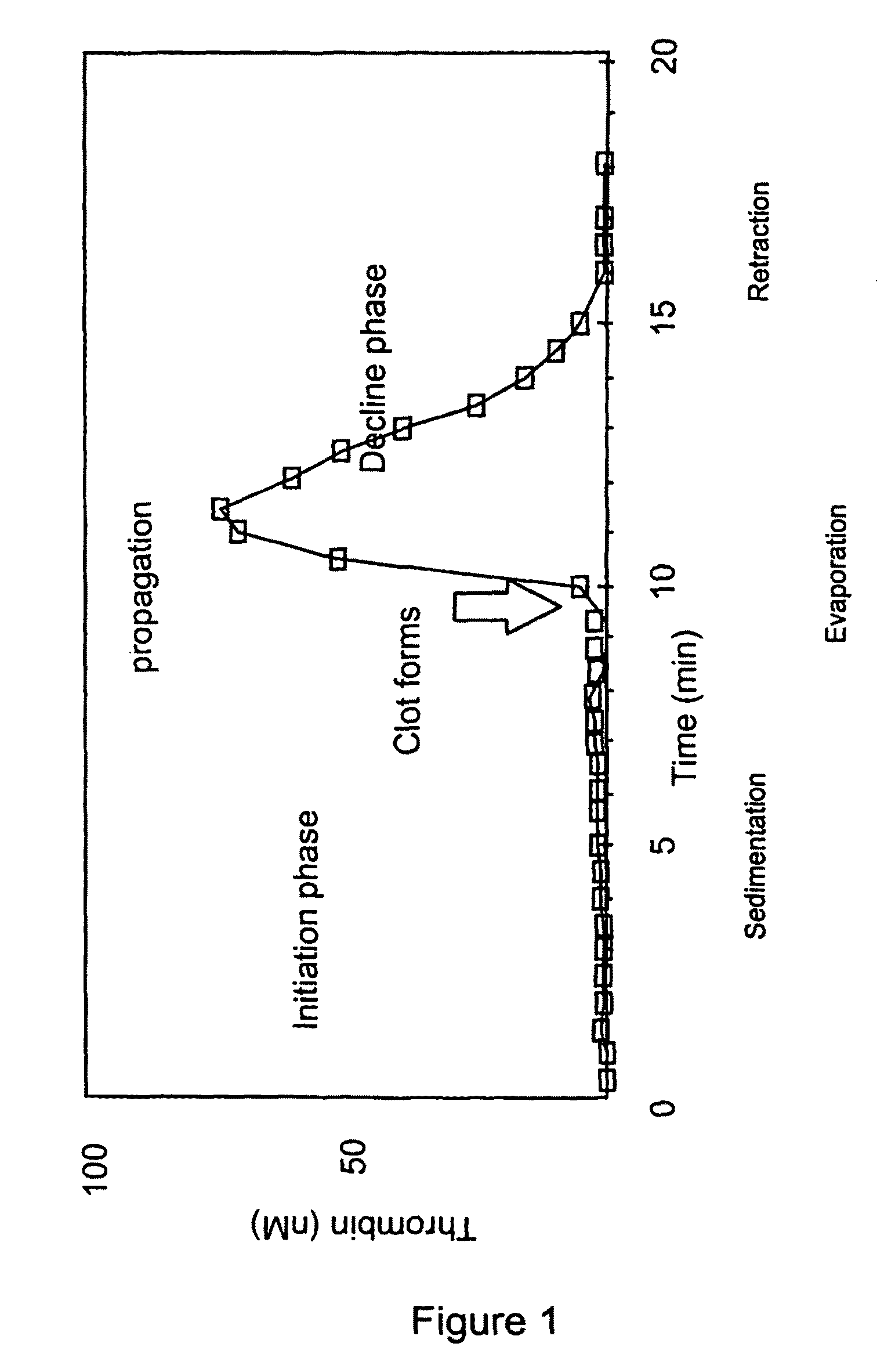
CROSS REFERENCE TO RELATED APPLICATIONS[0001]This application is a National Stage application filed under Rule 371 based on PCT / EP2006 / 004945 filed Apr. 26, 2006, which claims priority to EP 05290952.0 filed Apr. 29, 2005.[0002]The invention relates to a method of determining, especially measuring the time course of thrombin activity in vitro, i.e., measuring active thrombin in a sample, especially as it develops in a clotting sample consisting of whole blood. The result of measurement of thrombin activity can be represented by the so-called “thrombin generation curve” illustrated in FIG. 1.[0003]The invention also relates to means enabling the measurement of active thrombin following its generation in a sample in vitro. It is also directed to the use of said method of measurement for the detection or the monitoring of the condition of a patient, including for detection or monitoring of a pathological condition related to blood coagulation deficiency.[0004]The invention also concern...

Claims


Application Information

Patent Timeline
Patent Type & Authority Patents(United States)
IPC IPC(8): C12Q1/56
CPCC12Q1/56G01N2333/974G01N33/86
Inventor HEMKER, HENDRIK COENRAADBEGUIN, SUZETTEAL-DIERI, RAEDWAGENVOORD, ROBERTNIJHUIS, SEBASTIAANGIESEN, PETER
Owner SYNAPSE INC
Learn More