
Shift control apparatus for continuously variable transmission

a technology of transmission control and continuously variable transmission, which is applied in mechanical apparatus, instruments, digital data processing details, etc., can solve the problems of inability to obtain sufficient belt returnability, inability to optimize hydraulic pressure, and conventional control of belt clamping force not having the capability to optimize belt clamping force, etc., to achieve suitable shift control

Active Publication Date: 2014-12-30
TOYOTA JIDOSHA KK
View PDF12 Cites 5 Cited by
  • Summary
  • Abstract
  • Description
  • Claims
  • Application Information

AI Technical Summary

Benefits of technology

The present invention provides a shift control apparatus for a continuously variable transmission that can achieve suitable shift control when a vehicle is suddenly braked. This is achieved by using a wheel slip ratio as a value reflecting the road surface condition, and changing the shift speed of the continuously variable transmission in the downshift direction accordingly. The shift speed is increased when the wheel slip ratio is high, ensuring that the gear ratio of the continuously variable transmission is early increased to ensure good re-accelerability and startability of the vehicle. The challenge of ensuring accurate control when braking under sudden circumstances is solved by the shift control apparatus.

Problems solved by technology

However, if during sudden braking the hydraulic pressure to be supplied to the hydraulic actuator for the secondary pulley is simply set a fixed amount higher than before, this simple measure has no way to optimize the hydraulic pressure.
Therefore, the conventional control of belt clamping force does not have the capability to optimize the belt clamping force according to the road surface condition.
Specifically, if the aforementioned belt clamping force (set a fixed amount higher than before) is short of the optimum value, sufficient belt returnability may not be able to be obtained.
On the other hand, if the hydraulic pressure is higher than the optimum value, the power of an oil pump for providing the hydraulic pressure is increased more than necessary, which will reduce the energy efficiency.
However, this technique cannot provide an optimum shift speed appropriate to the road surface condition.

Method used


Image

  • Shift control apparatus for continuously variable transmission
  • Shift control apparatus for continuously variable transmission
  • Shift control apparatus for continuously variable transmission

Examples


Embodiment Construction

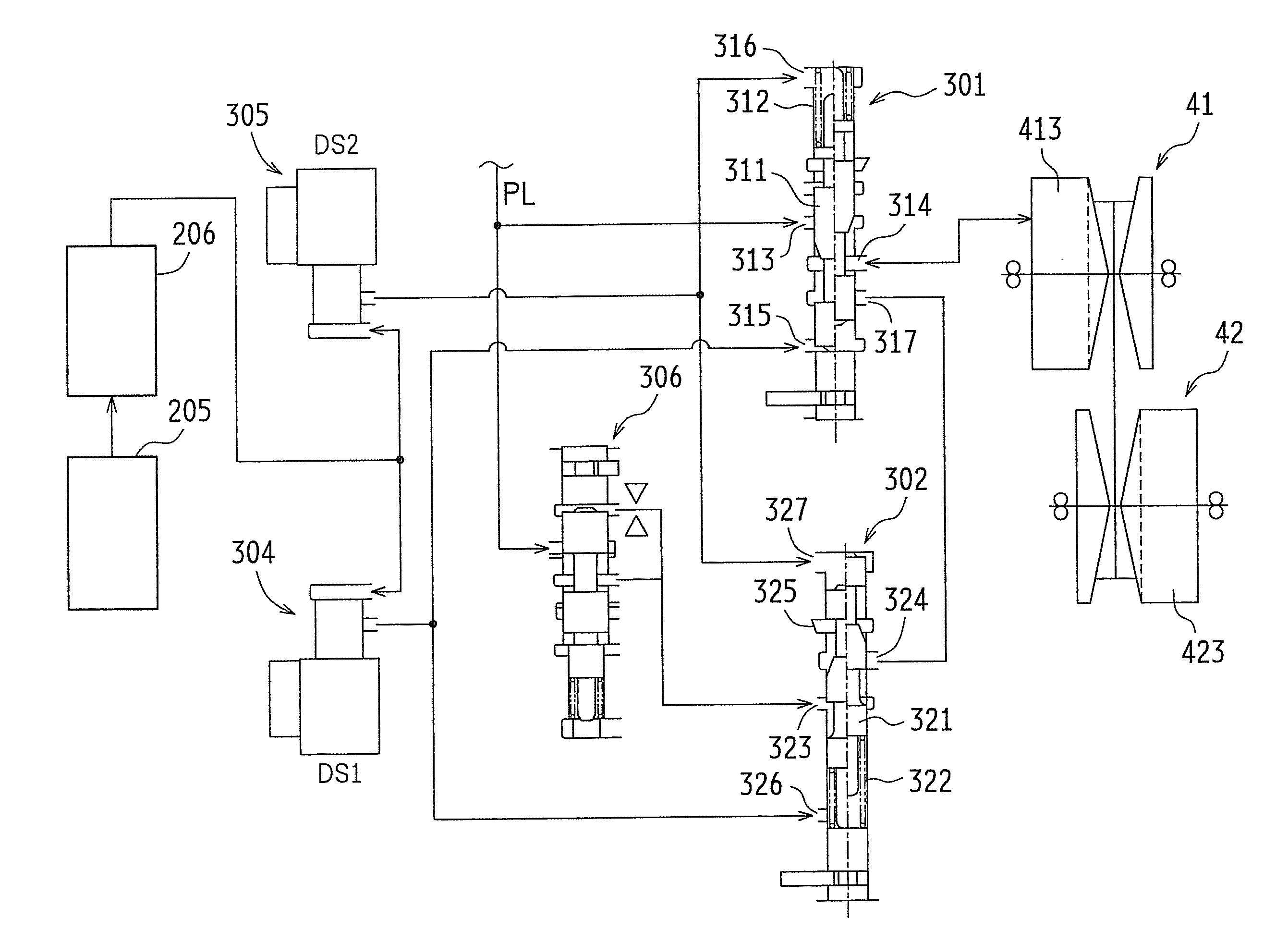
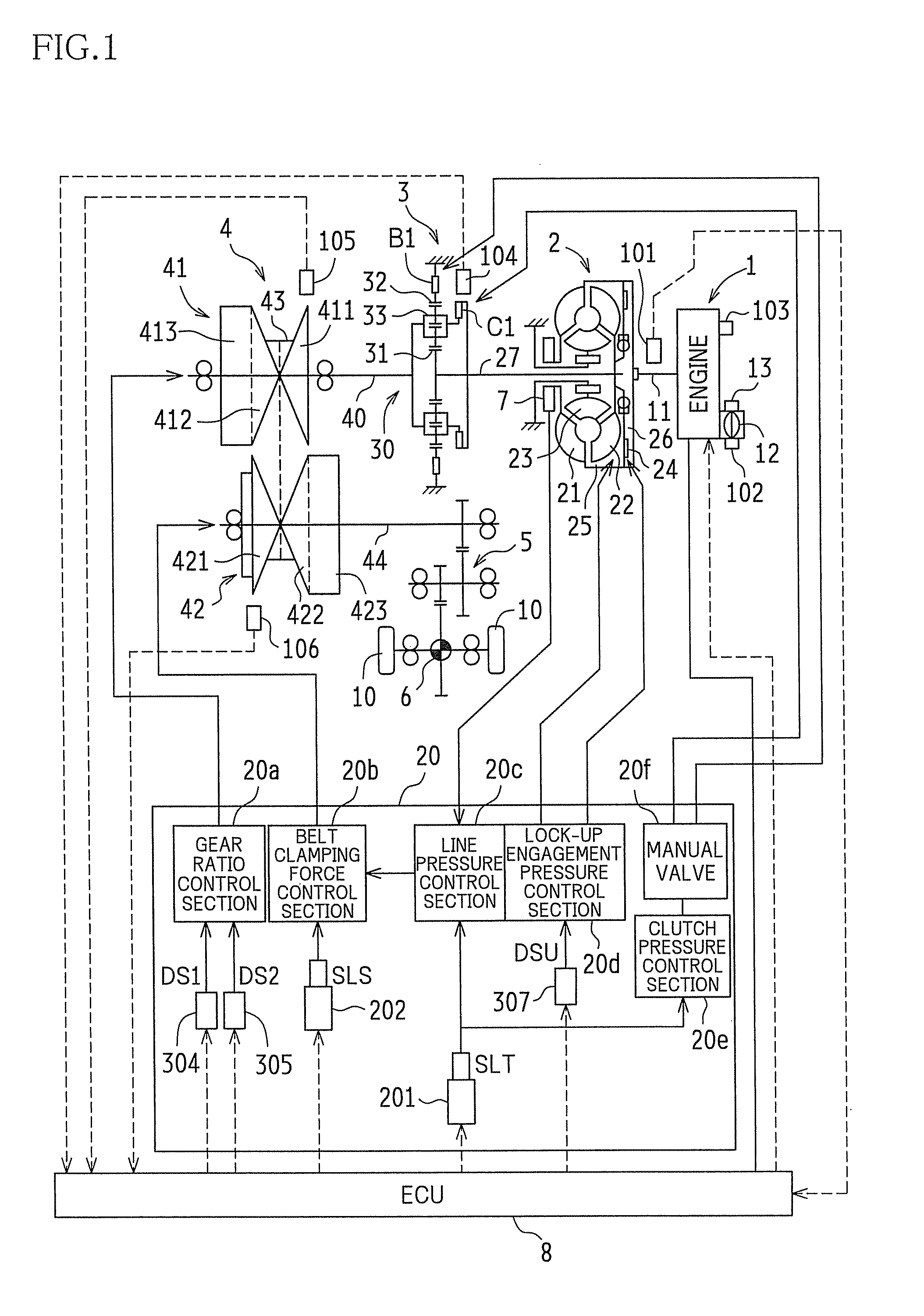
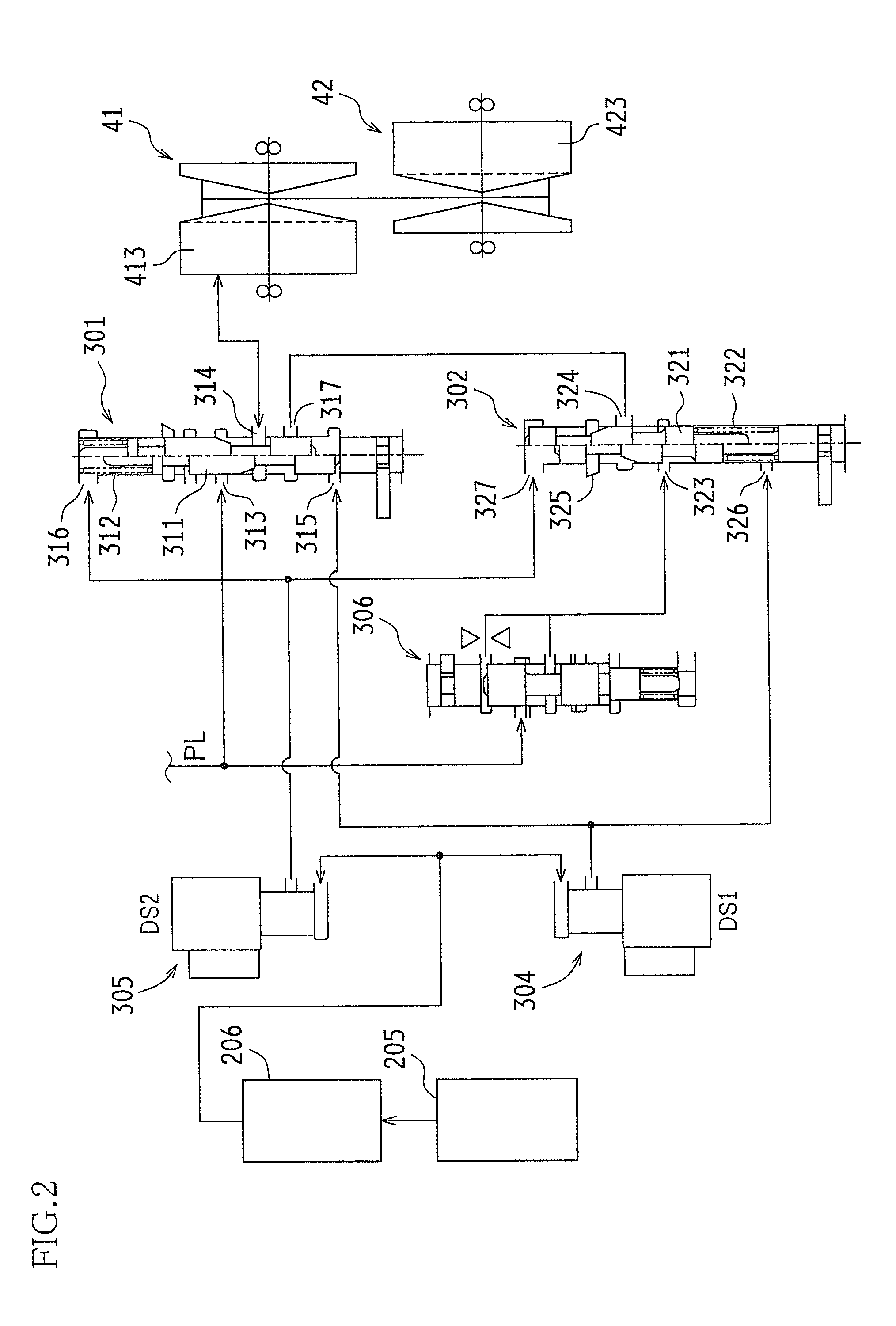
[0033]Hereinafter, a description will be given of an embodiment of the present invention with reference to the drawings. In this embodiment, a description will be given of the case where the present invention is applied to a vehicle equipped with a belt CVT (continuously variable transmission).

[0034]FIG. 1 is a schematic configuration diagram showing an example of the belt CVT-equipped vehicle according to this embodiment. The vehicle according to this embodiment is an FF (front engine-front drive) vehicle. The vehicle is equipped with an engine (internal combustion engine) 1 as the drive power source, a torque converter 2 as a fluid drive mechanism, a forward / reverse switching mechanism 3, a belt CVT 4, a reduction gear mechanism 5, a differential gear mechanism 6, an ECU (electronic control unit) 8, and so on.

[0035]Furthermore, a shift control apparatus for a CVT according to the present invention is implemented by a combination of the ECU 8, the belt CVT 4, a hydraulic control ci...


PUM


Abstract

Disclosed is a shift control apparatus for a continuously variable transmission configured to transmit power from a drive power source of a vehicle to a drive wheel of the vehicle. The shift control apparatus is configured to change a gear ratio of the continuously variable transmission with changes in vehicle speed and, during sudden braking of the vehicle, change a rate of change of the gear ratio (a shift speed) of the continuously variable transmission in a downshift direction depending upon a wheel slip ratio calculated from a wheel speed and the vehicle speed.

Description

CROSS-REFERENCE TO RELATED APPLICATION[0001]This application claims priority under 35 USC 119(a) to Patent Application No. 2012-271580 filed in Japan on Dec. 12, 2012, the entire contents of which are incorporated herein by reference.BACKGROUND[0002]1. Technical Field[0003]The present invention relates to a shift control apparatus for a continuously variable transmission installed in a vehicle. Particularly, the present invention relates to improvement in shift control during sudden braking of the vehicle.[0004]2. Related Art[0005]In a known belt CVT (continuously variable transmission) as disclosed in, for example, JP-A No. 2006-97757 or JP-A No. 2010-242935, a gear shift is made by increasing or reducing the individual widths of pulley grooves of a pair of pulleys around which a belt is winded.[0006]Specifically, while the belt is clamped by two pairs of sheaves, each pair constituting one pulley, in order to apply tension to the belt, the clamped state of the belt is changed by t...

Claims


Application Information

Patent Timeline
Patent Type & Authority Patents(United States)
IPC IPC(8): F16H61/662F16H61/02F16H61/66
CPCF16H61/66272F16H61/66259F16H2061/6605
Inventor NATORI, AKIO
Owner TOYOTA JIDOSHA KK
Learn More