Fitting for a vehicle seat

a vehicle seat and seat technology, applied in the direction of movable seats, gearing, hoisting equipment, etc., can solve problems such as wobbling movemen

Active Publication Date: 2015-01-13
KEIPER SEATING MECHANISMS CO LTD
View PDF20 Cites 19 Cited by
  • Summary
  • Abstract
  • Description
  • Claims
  • Application Information

AI Technical Summary

Benefits of technology

[0009]An essential reason for the fact that conditions are usually not ideal and not physically exactly correct when using flank forms of conventional gear teeth are the special requirements of an adjustable gear unit which, in addition to the usual task of translating a torque, also must fulfill the requirement of being self-locking and consequently blocking in both directions of load in its idle state and of being free of backlash at the same time. Known gear units and flank shapes which have been developed for them usually dispose of one single contact point or contact area between toothed wheel and toothed ring. This rolling area is nearly always close to the extension of eccentricity, i.e. to the line connecting the axes. With the generic gear fittings, the backlash free state during idle state is obtained by a change of the axes distance, i.e. by moving toothed wheel and toothed ring—in most cases by means of spring-loaded systems in the eccentric—towards each other, as far as this is possible in the corresponding state. In the extreme case, in a known tooth configuration, one single tooth bears with both of its flanks exactly in the extension of eccentricity. This state, during which the axis-reducing force and the contact points are nearly on the same line, naturally is rather instable and is therefore avoided according to the invention. For a very stable position, the teeth are configured in such a way that, in the backlash-free state, there is an angle in the order of a right angle between the contact points.

Problems solved by technology

The saving of a central pinion compared with a planetary gear system leads to the occurrence of a wobbling movement which is superimposed on the relative rotation of the fitting parts.

Method used


Image

  • Fitting for a vehicle seat
  • Fitting for a vehicle seat
  • Fitting for a vehicle seat

Examples


Embodiment Construction

[0018]Referring to the drawings in particular, a vehicle seat 1 for a motor vehicle has a seat part 3 and a backrest 4, the inclination of which is adjustable relative to the seat part 3. In order to adjust the inclination of the backrest 4, a drive shaft 7, which is arranged horizontally in the transition region between the seat part 3 and the backrest 4, is rotated manually, for example, by means of a handwheel 5, or in a motor-driven manner, for example by means of an electrical motor. On both sides of the vehicle seat 1, the drive shaft 7 engages in a fitting 10 so that it is rotationally secure, in a manner which will be described later. The drive shaft 7 defines the adopted directional data of a cylinder coordinate system.

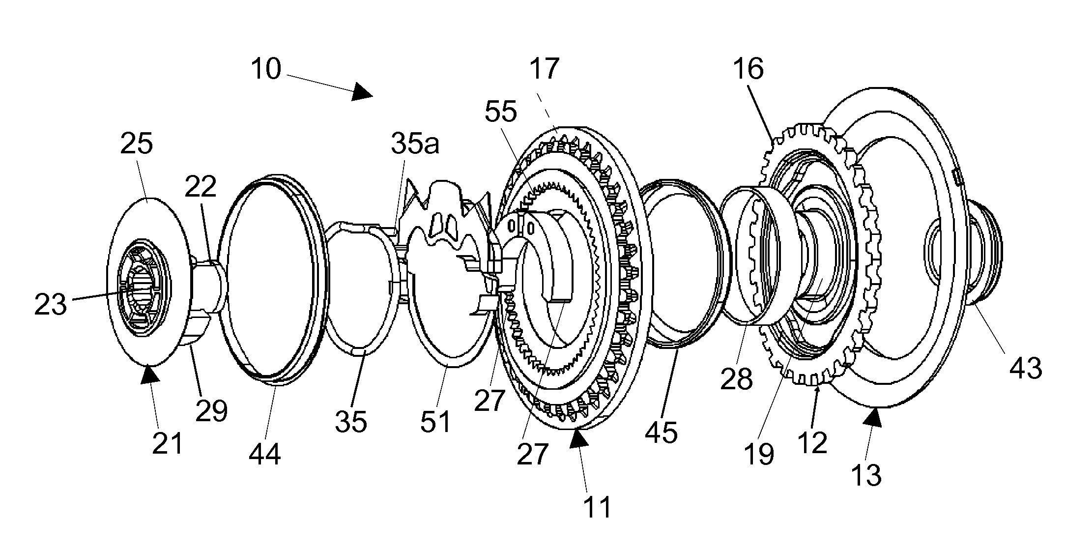
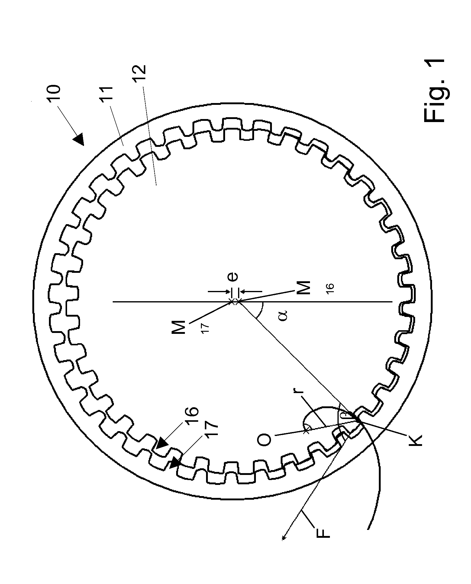
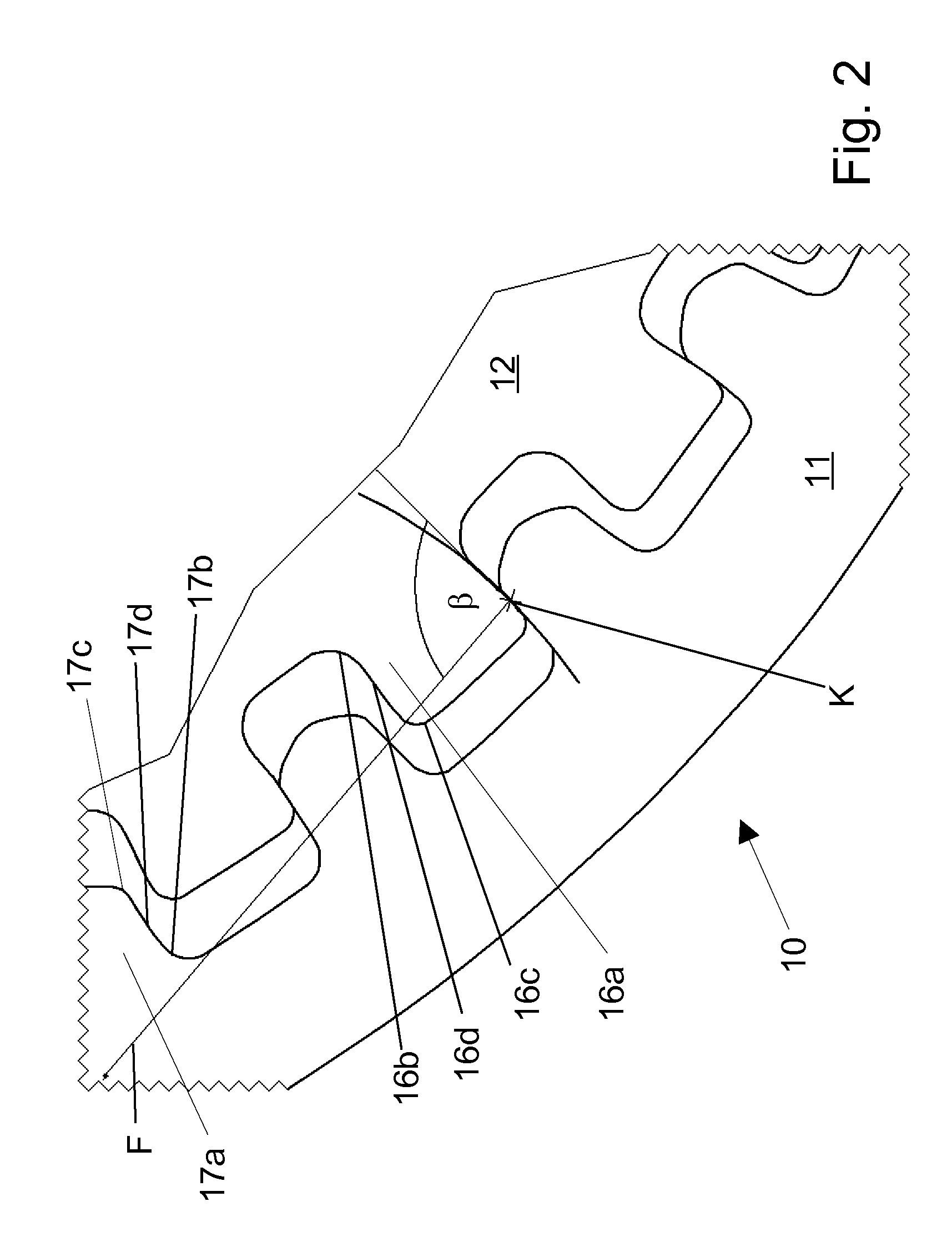
[0019]The fitting 10 has a first fitting part 11 and a second fitting part 12 which are rotatable relative to one another. Each of the two fitting parts 11 and 12 can be approximately inscribed in a circular disk shape. The two fitting parts 11 and 12 are pre...


PUM


Abstract

A fitting (10), in particular for a motor vehicle seat, having a first fitting part (11), on which a gear rim (17) is formed and a second fitting part (12) on which a gearwheel (16) is formed. The gearwheel meshes with the gear rim (17), whereby the two fitting parts (11, 12) are in geared connection with each other. The fitting also has a rotatably mounted, revolving eccentric driven by a driving element for driving a relative rolling motion of gearwheel (16) and gear rim (17). During this rolling motion a tooth flank (16d) of a tooth (16a) of the gearwheel (16) rests against a tooth flank (17d) of a tooth (17a) of the gear rim (17) at a contact point (K). The tooth flanks (16d, 17d) of the teeth (16a, 17a) of the gearwheel (16) and gear rim (17) resting against each other at the contact point (K) each follow the course of a portion of a respective logarithmic spiral.

Description

CROSS REFERENCE TO RELATED APPLICATIONS[0001]This application is a United States National Phase application of International Application PCT / EP2010 / 005103 and claims the benefit of priority under 35 U.S.C. §119 of German Patent Application DE 10 2009 040 453.8 filed Aug. 28, 2009, the entire contents of which are incorporated herein by reference.FIELD OF THE INVENTION[0002]The invention relates to a fitting for a vehicle seat, in particular for a motor vehicle seat, having a first fitting part on which is formed a toothed ring, a second fitting part on which is formed a toothed wheel which meshes with the toothed ring, as a result of which the two fitting parts are in gear connection with each other, a rotatably supported circumferential eccentric, driven by a driver, for driving a relative rolling movement of the toothed wheel and the toothed ring.BACKGROUND OF THE INVENTION[0003]A fitting of this type is known from DE 40 34 843 C2, such fitting serving as a backrest adjusting mech...

Claims


Application Information

Patent Timeline
Patent Type & Authority Patents(United States)
IPC IPC(8): B60N2/235B60N2/225F16H1/32F16H55/08
CPCB60N2/2252F16H1/32F16H2055/0893
Inventor SCHULER, ROLFBOSSMANNS, BERNDKALMUS, KARSTENTHIEL, PETER
Owner KEIPER SEATING MECHANISMS CO LTD
Why Eureka
Try Eureka