Developing device and image forming apparatus

a technology of developing device and image forming apparatus, which is applied in the direction of electrographic process apparatus, instruments, optics, etc., can solve the problems of deterioration of developer, affecting the development of the product, so as to reduce the effect of reducing the unsteadiness of the coa

Active Publication Date: 2015-01-13
CANON KK
View PDF16 Cites 1 Cited by
  • Summary
  • Abstract
  • Description
  • Claims
  • Application Information

AI Technical Summary

Benefits of technology

[0014]The present invention is directed to suppress attachment of a developer to a surface of a guide member and reduce unsteadiness of a coat caused by poor feeding of the developer.

Problems solved by technology

This phenomenon tends to take place particularly when the developer is deteriorated.
The deterioration of the developer means that, due to a collision between the toner and the developing sleeve or between the toners, the toner and particularly a convex part of the toner is damaged, or an external additive on a toner surface is buried in the toner surface.
This developer deterioration is prone to take place mainly when an image with a low consumption of the toner continues to be output for a long time, because the developer is agitated inside the developing device for a long time.
Thus, if this developer deterioration takes place, the adhesive force of the toner is increased.
As a result, problems such as the coating on the developing sleeve 108 failing to be uniform occur.

Method used


Image

  • Developing device and image forming apparatus
  • Developing device and image forming apparatus
  • Developing device and image forming apparatus

Examples


first embodiment

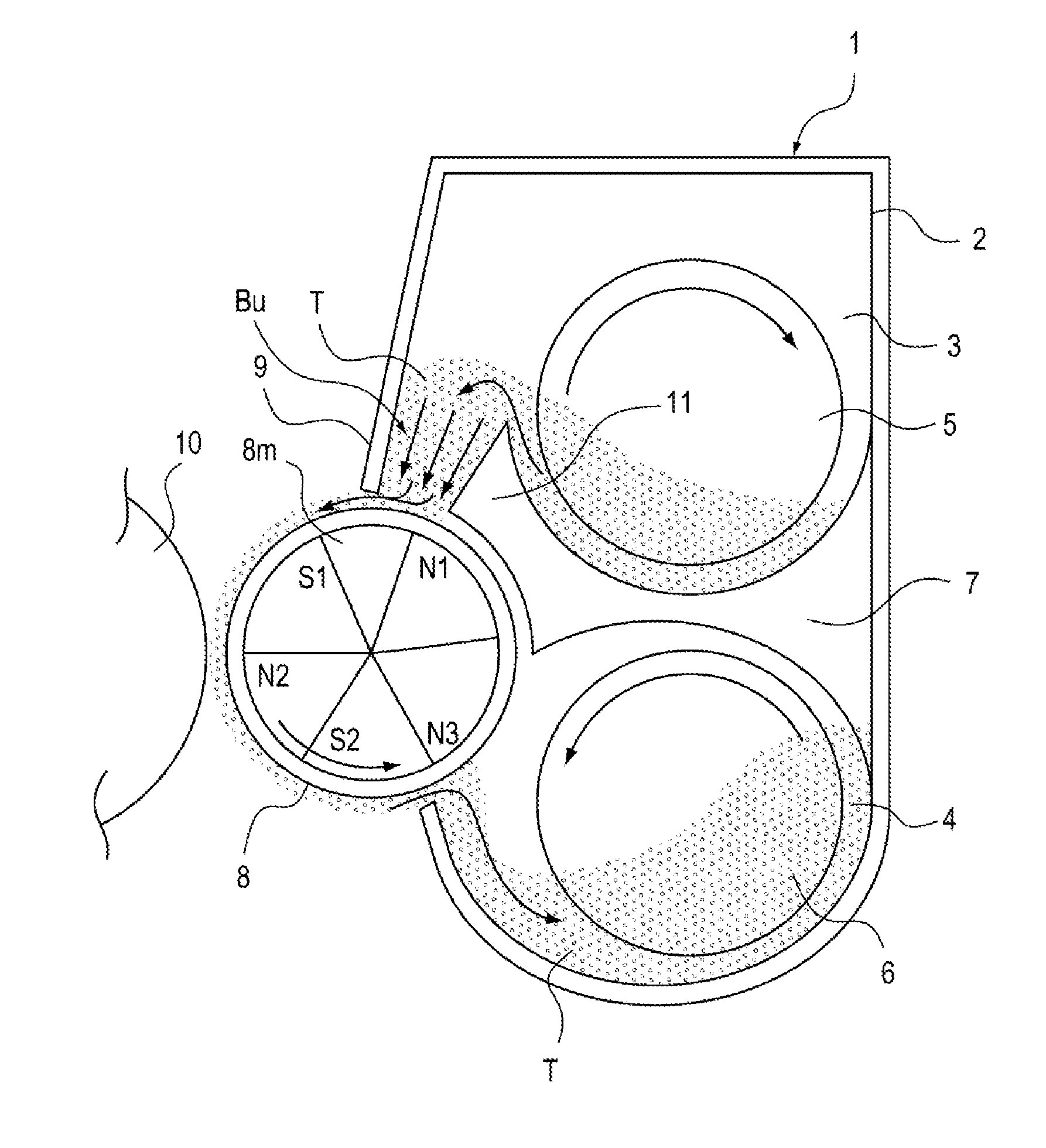
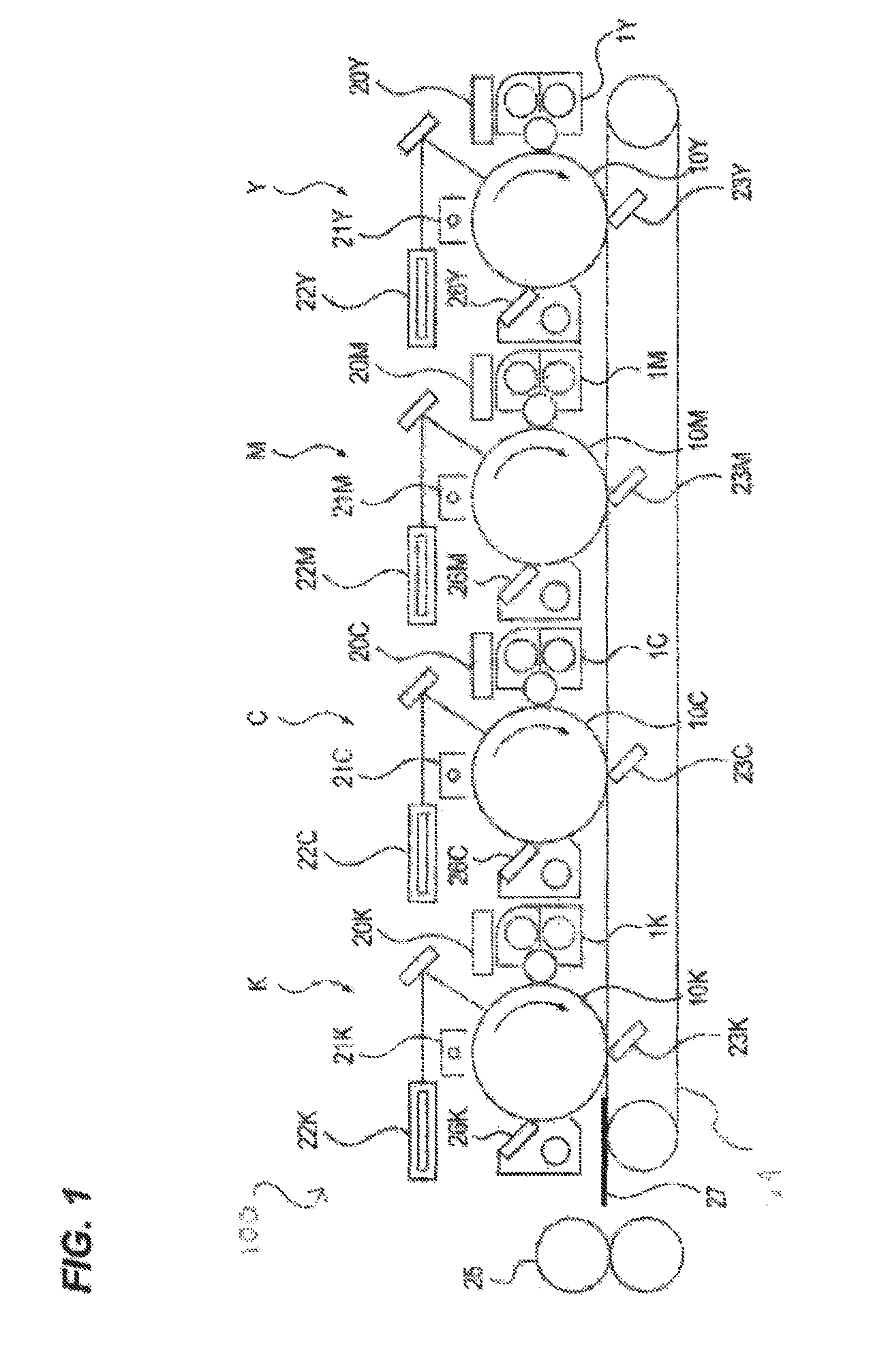
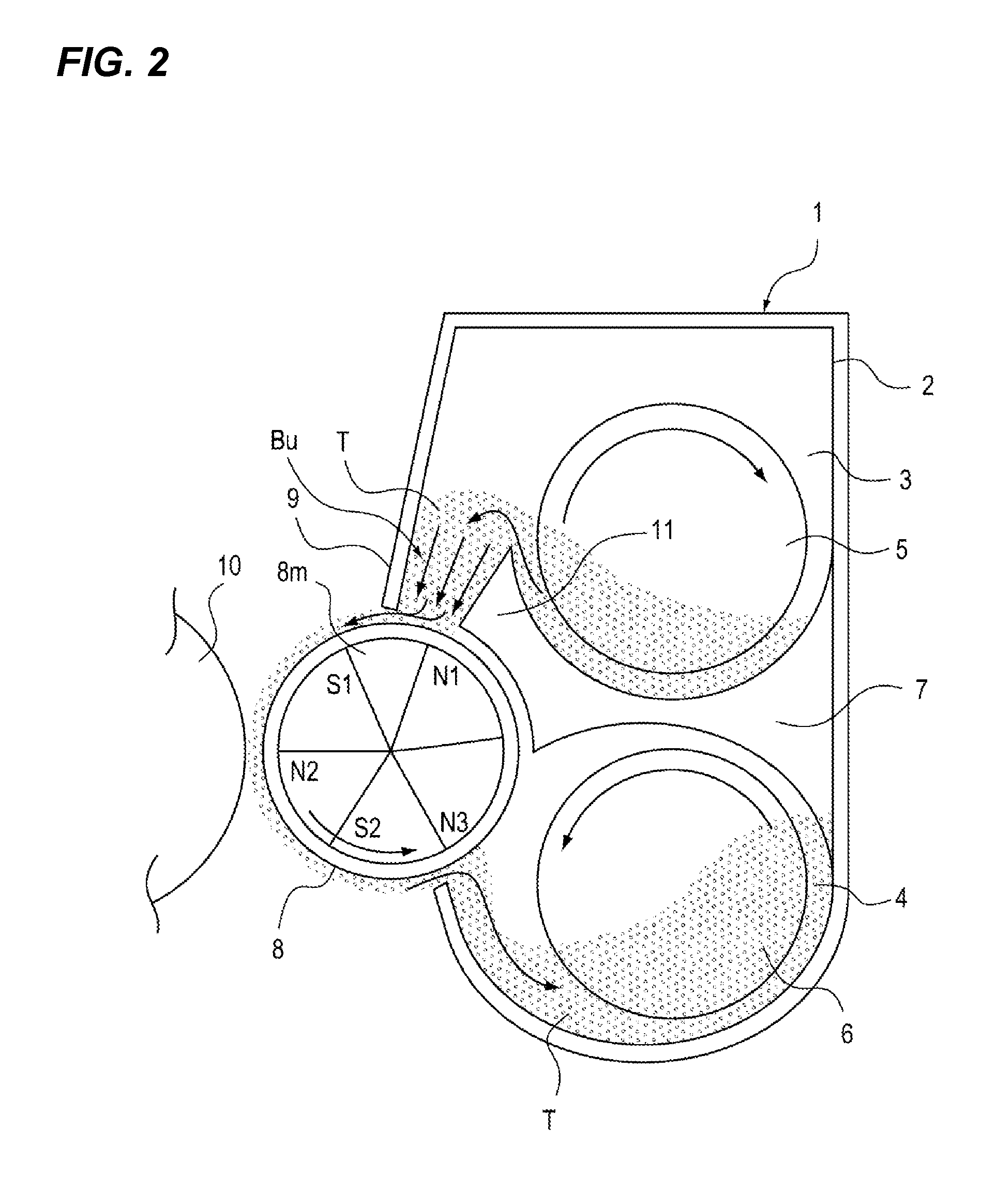
[0045]FIG. 1 is a view for describing a positional relation between an image forming apparatus and a developing device of a first embodiment. In the image forming apparatus 100, a positional relation between a photosensitive drum (image bearing member) 10 and a developing device (developing portion) 1 at each one of Y, M, C, and K stations is illustrated in FIG. 1.

[0046]The Y, M, C, and K stations have substantially the same configuration, and form yellow (Y), magenta (M), cyan (C), and black (K) images in a full-color image, respectively. In the following description, for example, the developing device 1 will commonly indicate a developing device 1Y, a developing device 1M, a developing device 1C, and a developing device 1K at the respective Y, M, C, and K stations.

[0047]First, an operation of the entire image forming apparatus will be described based on FIG. 1. A photosensitive drum 10 is installed so as to be freely rotatable. The photosensitive drum 10 is uniformly charged by a ...

second embodiment

[0111]A second embodiment of the present invention is described. Since a basic configuration is the same as in the first embodiment, elements having a function and configuration that are substantially identical or equivalent to those of the first embodiment are indicated with the same reference numerals, and detailed description thereof is omitted herein. Hereinafter, only constituent portions unique to the present embodiment will be described in detail.

[0112]In the first embodiment, the angle α of the tip surface of the guide member 11 is set to be greater than the angle β of the external force F which the developer receives relative to the horizontal plane on the surface of the guide member 11, and the sticking of the developer to the surface of the guide member 11 is reduced.

[0113]However, as described previously, β has a tendency to be gradually increased in proportion to the distance from the surface of the developing sleeve. For this reason, when the length of the guide member...

third embodiment

[0123]A third embodiment of the present invention is described. Since a basic configuration is the same as in the first embodiment, elements having a function and configuration that are substantially identical or equivalent to those of the first embodiment are indicated with the same reference numerals, and detailed description thereof is omitted herein. Hereinafter, only constituent portions unique to the present embodiment will be described in detail.

[0124]FIG. 20 is a cross-sectional view for describing a guide member of a third embodiment. As illustrated in FIG. 20, in the present embodiment, the surface of the guide member 11 is set to a curved surface. Thus, an angle α which a tangent at each point on the surface of the guide member 11 forms with respect to the horizontal plane at that point is set to an angle β which an external force F, which is a resultant force of a magnetic force Fm and a gravitational force Fg which the developer receives at that point, forms with respec...


PUM


Abstract

A developing device includes a developer carrier which carries a developer containing a toner and a carrier, and a developing chamber which feeds the developer to the developer carrier. In addition, a conveying member conveys the developer of the developing chamber, and a regulating member regulates an amount of the developer coated on the developer carrier. A guide portion guides the developer to the developer carrier and forms a buffer portion that temporarily contains the developer fed from the developing chamber between the regulating member and the guide portion. The guide portion has a facing surface opposing the developer carrier along a front surface of the developer carrier and a guiding surface which guides the developer from an upper edge of the guide portion to a downstream side of the facing surface in a rotational direction of the developer carrier. Magnetic poles inside the developer carrier are disposed so that a magnetic direction effecting the carrier in the developer on the guiding surface is set in a direction to leave the guiding surface in a range from an upper portion toward a lower portion of the guiding surface.

Description

BACKGROUND OF THE INVENTION[0001]1. Field of the Invention[0002]The present invention relates to a developing device that forms an image using an electrophotographic system, and an image forming apparatus having the same.[0003]2. Description of the Related Art[0004]Conventionally, developing devices include those that use a two-component developer having non-magnetic toner particles (toner) and magnetic carrier particles (carrier) as a developer. For example, in Japanese Patent Laid-Open No. 05-333691, the developing device using the two-component developer is generally configured as illustrated in FIG. 27. FIG. 27 is an explanatory view of a conventional developing device.[0005]A conventional developing device 101 is equipped with a developing container 102 containing the developer, and has a developing sleeve 108 that is a developer carrier at an opening facing a photosensitive drum (not illustrated) that is an image bearing member. Thus, a developing chamber 103 and an agitating ...

Claims


Application Information

Patent Timeline
Patent Type & Authority Patents(United States)
IPC IPC(8): G03G15/08G03G15/09
CPCG03G15/0812G03G15/09G03G2215/0822
Inventor MATSUMOTO, ATSUSHI
Owner CANON KK
Why Eureka
Try Eureka