Printing apparatus and method for removing contaminants in printing apparatus
a technology of printing apparatus and printing machine, which is applied in the direction of printing press, metal working apparatus, printing, etc., can solve problems such as poor printing, and achieve the effect of reducing the occurrence of poor printing and suppressing the attachment of contaminants
- Summary
- Abstract
- Description
- Claims
- Application Information
AI Technical Summary
Benefits of technology
Problems solved by technology
Method used
Image
Examples
modification example 1
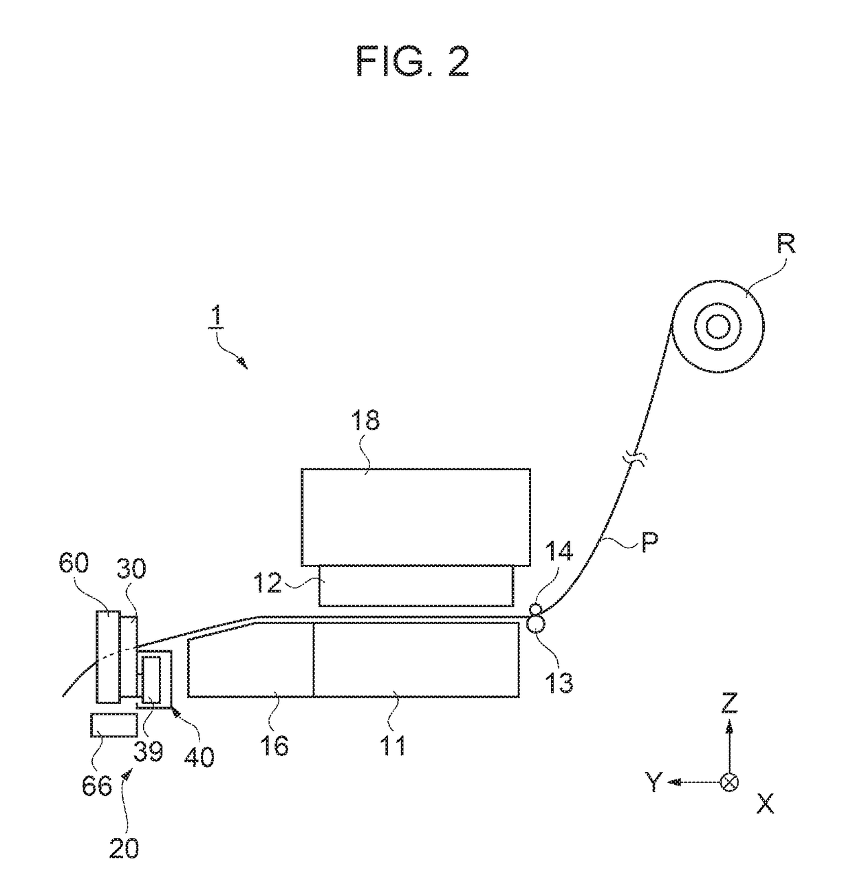
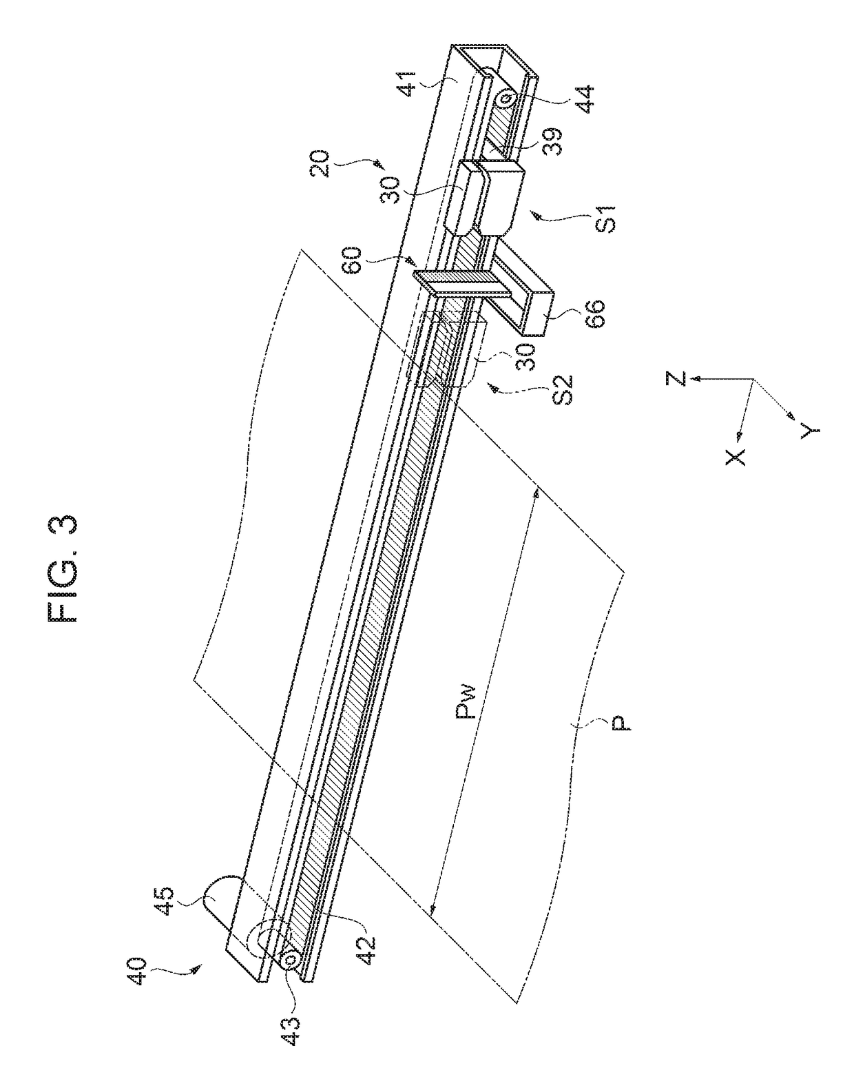
[0063]In the above-described embodiment, the cutting portion 20 is arranged on one surface side of the housing unit (downstream side of the cutting portion 20 in the transport direction); however, the structure is not limited to this. The contact portion 60 may be provided on the other surface side of the housing unit 32 (upstream side of the cutting portion 20 in the transport direction) or may be provided on both surface sides of the housing unit 32. That is, it is preferable to arrange the contact portion 60 taking into consideration the position at which the contaminants such as paper powder or the like attach to the housing unit 32. By doing this, it is possible to efficiently remove contaminants such as paper powder or the like attached to the housing unit 32.
modification example 2
[0064]The form of the contact portion 60 of the above-described embodiment is that of an anti-static brush; however, the structure is not limited to this. For example, the form of the contact portion 60 may be, other than an anti-static brush, a resin member such as a sponge or the like, or a fabric member or the like. In this way, it is possible to realize the same effect as above. Further, in the case where a resin member, cloth member, or the like serving as the contact portion 60 is used, it is preferable to divide the member into a plurality of members and arrange the members in a line in a direction (Z-axis direction) that intersects the movement direction (X-axis direction) of the cutter unit 30. Consequently, it is possible for the resin member, cloth member, or the like to contact the housing unit 32 so as to follow the shape of the surface of the housing unit 32 and it is possible to remove contaminants such as paper powder attached to the housing unit 32.
modification example 3
[0065]The lengths of the fibers 61 of the contact portion 60 of the above-described embodiment are set so as to be uniform; however, the structure is not limited to this. The length of the fibers 61 may be suitably changed in accordance with the shape of the surface of the housing unit 32 or the like. Moreover, the fibers 61 may be arranged so as to have different elasticity in accordance with the shape of the housing unit 32. By doing this, furthermore, it is possible to efficiently remove contaminants such as paper powder or the like attached to the housing unit 32. Moreover, it is possible to decrease the contact load on the housing unit 32 by the contact portion 60.
PUM
 Abstract
Description
Claims
Application Information
 - R&D
- Intellectual Property
- Life Sciences
- Materials
- Tech Scout
- Unparalleled Data Quality
- Higher Quality Content
- 60% Fewer Hallucinations
Browse by: Latest US Patents, China's latest patents, Technical Efficacy Thesaurus, Application Domain, Technology Topic, Popular Technical Reports.
© 2025 PatSnap. All rights reserved.Legal|Privacy policy|Modern Slavery Act Transparency Statement|Sitemap|About US| Contact US: help@patsnap.com


