
Dual-channel hot standby system and method for carrying out dual-channel hot standby

a dual-channel hot standby and hot standby technology, applied in the field of industrial control, can solve the problems of insecure state, blind spots for the supervision of dual-channel status, and relatively greater risks to the normal operation of the whole system

Active Publication Date: 2015-01-13
BEIJING JIAOTONG UNIV
View PDF11 Cites 0 Cited by
  • Summary
  • Abstract
  • Description
  • Claims
  • Application Information

AI Technical Summary

Benefits of technology

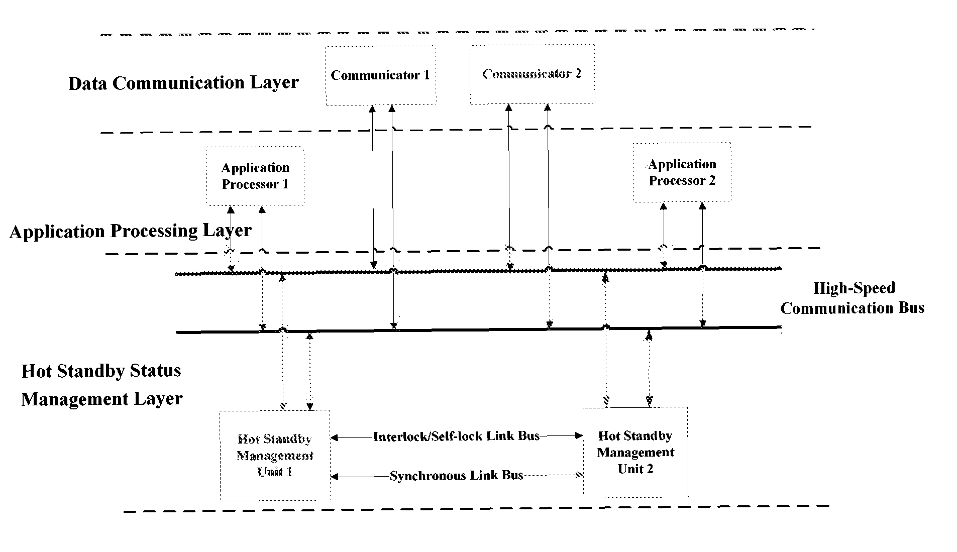
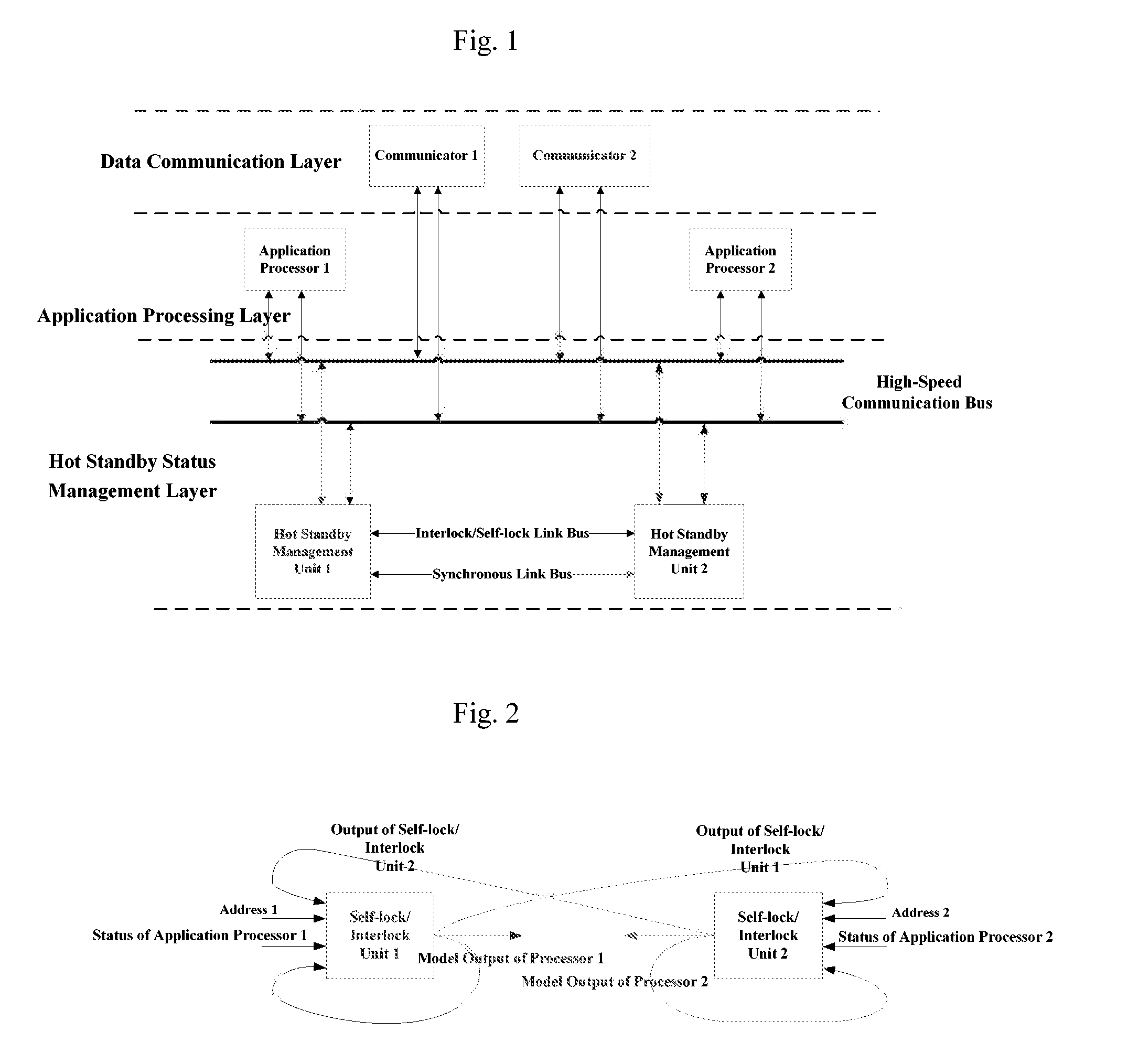
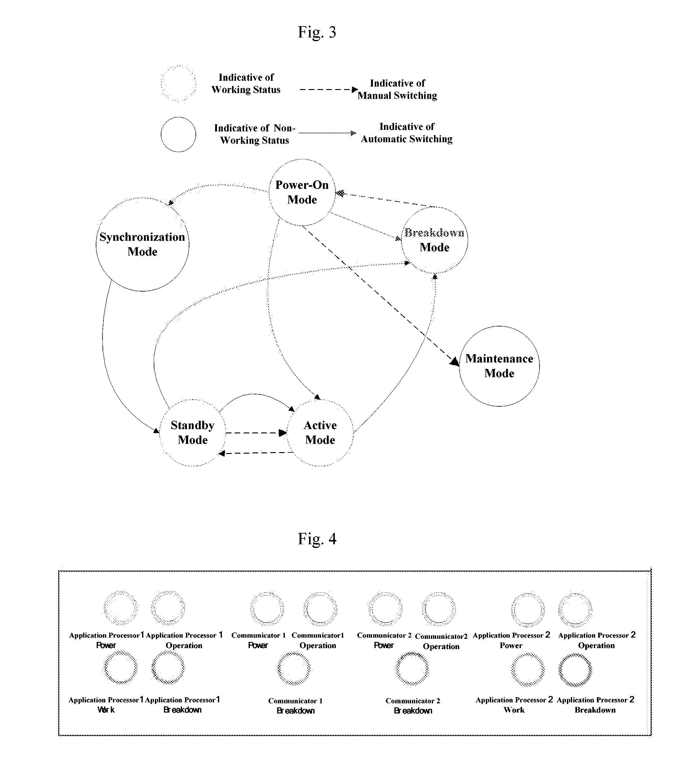
[0021]The above-mentioned technical solutions are advantageous in that, it designs a dual-channel hot standby system having hierarchical structure, and controls the presetting and switching of active and standby statuses by means of switch units (that is, the hot standby management units) therein as determination equipments form a third part; Besides, the switch unit uses a design of redundant hardware to select a channel in normal operation as the one in active status by means of the self-lock / interlock logic, so as to avoid the “dual-channel-active” or “dual-channel-standby” status which may be occurred when two channels make determination for each other. At the same time, a switch unit can also output synchronous signals to ensure a synchronization of the control cycles of the two channels, and can monitor the working statuses of the two channels in real-time by workflow control codes, which reduces the time for responding to breakdowns. The data exchange among the three layers in said structure is realized by a high-speed communication bus, which satisfies the real-time requirements of the whole dual-channel hot standby system. The hot standby management unit, the high-speed communication bus and the communicators all adopt redundant structures, which can improve the reliability and availability of the whole system. In addition, in order to ensure a seamless switching of active and standby statuses, three of the following ways are used at the same time: 1) the application processor, before it enters into the standby mode, conducts a synchronization in the synchronous mode according to the data from the application processor which is in the active mode; 2) making the two application processors to be in the working status with synchronous cycles; 3) ensuring a consistency of the input data sent to the two application processors by means of the data communication layer.

Problems solved by technology

This kind of way is short of supervision from a third party, so that when the heartbeat line is out of order, a “standby” channel may mistakenly become an “active” one, which generates a status of dual-channel-active, influences the transmission and control of messages, hence an insecure state may be occurred.
However, the function of such switch unit is just limited to the presetting and switching between “active” and “standby” statuses, and it's unable to control the synchronization status between two channels, which results in blind spots for the supervision of dual-channel status.
At the same time, the breakdown of a switch unit short of redundancy configuration may cause relatively greater risks to the normal operation of the whole system.

Method used


Image

  • Dual-channel hot standby system and method for carrying out dual-channel hot standby
  • Dual-channel hot standby system and method for carrying out dual-channel hot standby
  • Dual-channel hot standby system and method for carrying out dual-channel hot standby

Examples


Embodiment Construction

[0028]The following embodiments are described in way of examples for explaining the present invention, but not to limit the scope thereof

[0029]An embodiment of the present invention provides a dual-channel hot standby system and a method for carrying out dual-channel hot standby by using the same.

[0030]The dual-channel hot standby system adopts a design of hierarchical structure which can be divided into a hot standby status management layer, an application processing layer and a data communication layer. A hierarchical structural view of the system is shown in FIG. 1.

[0031]The hot standby status management layer adopts a design of redundancy hardware, which comprises of two hot standby management units. The hot standby management unit 1 monitors the working status of an application processor 1, and sends mode codes to the application processor to inform its working mode. In the same way, a hot standby management unit 2 controls working status of an application processor 2. The two ...


PUM


Abstract

A dual-channel hot standby system and a method for carrying out dual-channel hot standby, the system comprises a hot standby status management layer including two hot standby management units, an application processing layer including two application processors, and a data communication layer including two communicators; the hot standby status management layer is used for controlling the setting and switching between a active status and a standby status of the two application processors, monitoring the working status of the data communication layer, and carrying out synchronization of the control cycles for the two channels of the system; wherein one of the hot standby management units controls one of the application processors, and together constitute a channel of the system therewith; the data communication layer is used for receiving data from outside, and forwarding the data to the application processing layer. The present invention avoids the occurrence of “dual-channel-active” or “dual-channel-standby” status; ensures synchronization of the control cycles of two channels; reduces the time of the system for responding to breakdowns; meets the real-time requirements; enhances the reliability and availability of the system; and ensures a seamless switching between active and standby statuses.

Description

CROSS REFERENCE TO RELATED APPLICATION[0001]This application claim the benefit and priority to and is a U.S. National Phase of PCT International Application Number PCT / CN2011 / 001187, filed on Jul. 20, 2011, designating the United States of America, which claims priority under 35 U.S.C. §119 to Chinese Application Number 201010235370.5 filed on Jul. 22, 2010.TECHNICAL FIELD[0002]The present invention relates to the technical field of industrial control, in particular to a dual-channel hot standby system and a method for carrying out dual-channel hot standby.BACKGROUND ART[0003]In fields of industrial control like railway, electric power, iron and steel-producing and petrochemical industry, there are relatively strict requirements for availability and reliability of control systems. The dual-channel hot standby systems are widely used due to the higher availability and reliability, at the same time they have certain capability of fault-tolerance and are convenient for maintenance.[000...

Claims


Application Information

Patent Timeline
Patent Type & Authority Patents(United States)
IPC IPC(8): G06F11/00G06F11/20H04L1/00H04L1/22
CPCH04L1/22G06F11/2023H04L2001/0094
Inventor TANG, TAOMA, LIANCHUANWANG, XIYUAN, BINBIN
Owner BEIJING JIAOTONG UNIV
Learn More