Controllable lighting system

a technology of lighting system and control panel, which is applied in the direction of lighting and heating apparatus, semiconductor devices of light sources, light source combinations, etc., can solve the problems of system thickness and bulk, often not thin and compact, and achieve the effect of thin and compa

Inactive Publication Date: 2015-01-27
SIGNIFY HLDG BV +1
View PDF19 Cites 5 Cited by
  • Summary
  • Abstract
  • Description
  • Claims
  • Application Information

AI Technical Summary

Benefits of technology

[0004]It is an object of the present invention to overcome these problems, and to provide a lighting system that can create a changeable lighting pattern and that is thin and compact.
[0006]The spreading optical element defines an available angular emission range, within which all light emitted by the system will be contained. The control of the light emitting elements then effects a selection of an angular subrange of this available range. By controlling the selection of this subrange the resulting illumination pattern can be varied. This allows the light emitted from the spreading optical element to be varied without varying any physical parts of the lighting system, because the controller now controls each of the light emitting elements, by e.g. dimming one or more of the light emitting elements or by switching one or more of the light emitting elements off. In this way it is e.g. possible to scan light beams, change beam size and shape, since the spreading optical element can convert light emitted from a cluster of light emitting elements into one beam. By changing the position and / or size of the cluster of light emitting elements it is possible to change the location and / or size of the spots.
[0012]The lighting system may further comprise a light sensor, such that in use the light sensor measures prescribed light emission angle ranges and the controller compares these with a requested light emission angle ranges. In this manner the light emission ranges can automatically be adjusted to a prescribed light emission range without any user assistance. For example the light sensor and the light emitting elements may be electrically and mechanically integrated in a lighting unit, so that a compact design is achieved. By use of a sensor it is possible to automatically adapt the light pattern, i.e. it is possible to adapt the light pattern without moving the lamp or by input to the lamp. This is an advantage since when a lamp is positioned in a home the position of the lamp may change once in a while unintentionally due to small movements and shifts, which for instance is a result of pushes against the lamp during cleaning, or intentionally. In this way it is e.g. possible to vary the beam angle, shift the beam angle, vary the gradient of illumination, and vary the gradient of color if colored red, green and blue LEDs are used. The lighting system may e.g. comprise an indicator adapted to transmit light information, and wherein the light sensor is adapted to sense the light information transmitted to the light sensor, and transmit this transmitted light information to the controller, the controller being adapted to link the transmitted light information into a light emission pattern. This provides for an easy use of the lighting system.
[0013]The spreading optical element may e.g. be a negative or positive lens, a negative or positive Fresnel lens, or a patterned array of micro-prismatic beam deflectors. It is an advantage of the Fresnel lens that it is thin and compact compared to a conventional lens, and besides that it is much easier to manufacture than a patterned array of micro-prismatic beam deflectors. If a positive lens or a positive Fresnel lens is used it provides for longer working distances in order for the light to spread after it has been focused.

Problems solved by technology

But a problem with this arrangement is that in order to achieve a moving light pattern the light source needs to be moved by e.g. a mechanical arrangement.
As a consequence of that, such systems are often not thin and compact but relatively thick and bulky.

Method used


Image

  • Controllable lighting system
  • Controllable lighting system
  • Controllable lighting system

Examples


Embodiment Construction

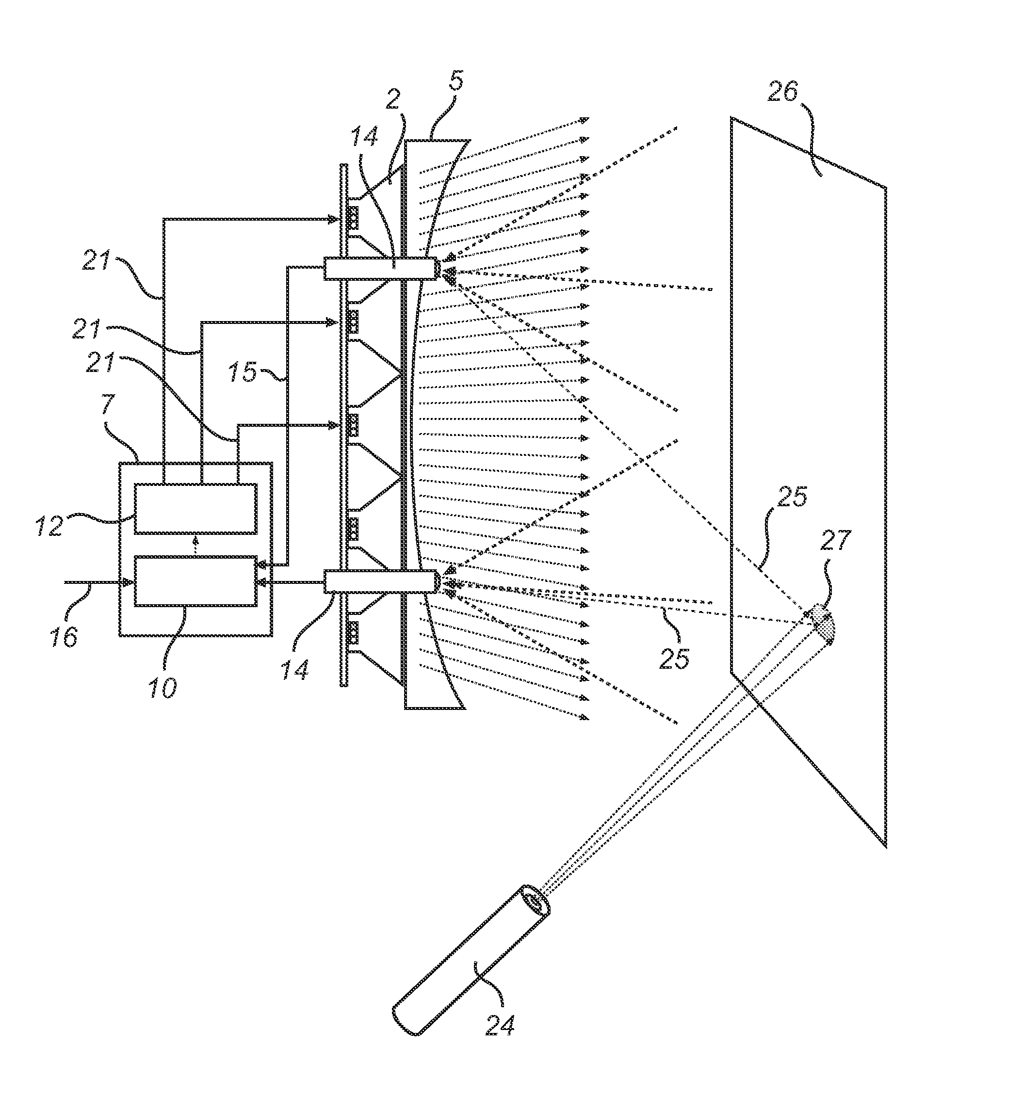
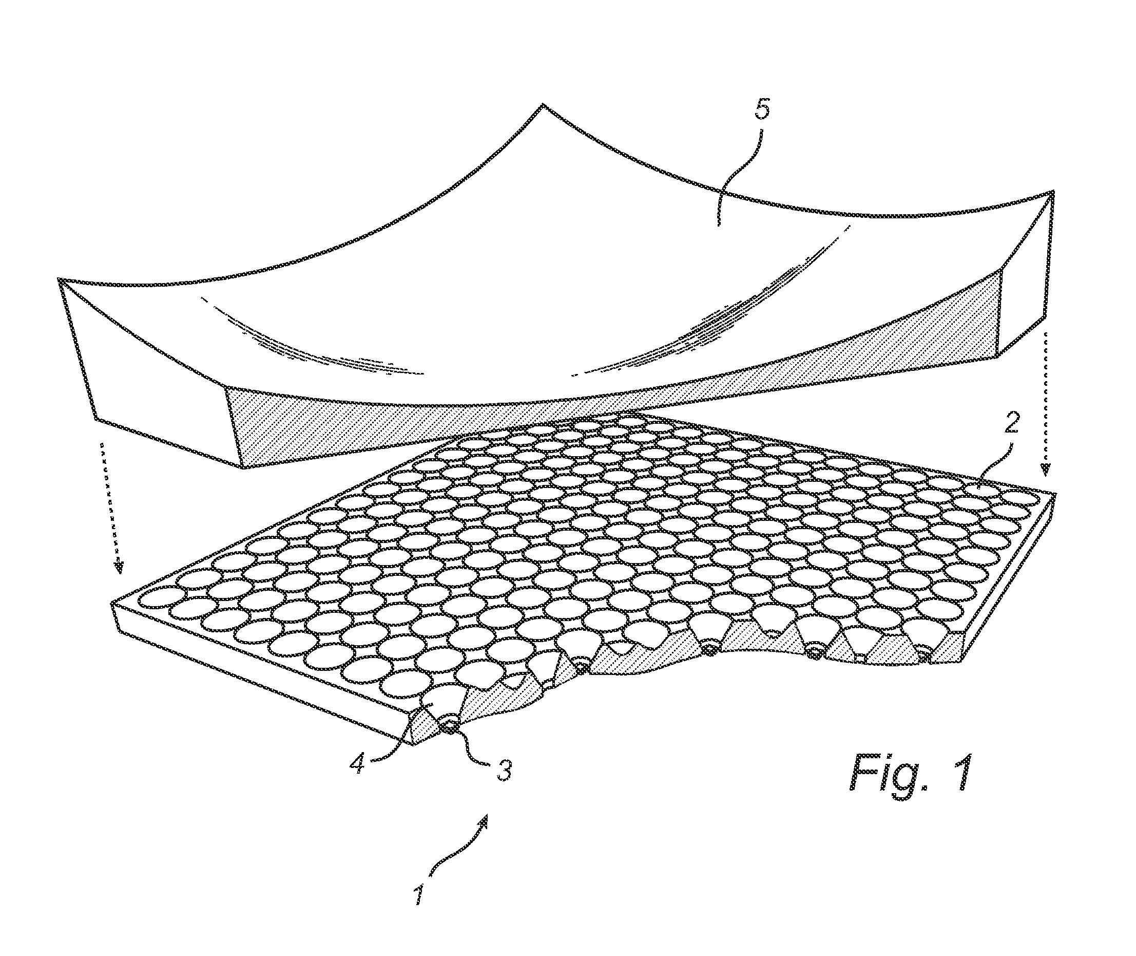
[0024]The lighting unit in the illustrated example in form of a lamp 1 in FIG. 1 comprises an array of collimated light sources 2 arranged in a two dimensional array wherein the two dimensional array is a rectangular 16×16-array. The collimated light sources 2, each comprises a plurality of the controllable light emitting elements 3 and a beam collimating optics 4, wherein each collimated light source 2 includes a red, a blue, and a green light emitting element 3, preferably in form of a red, a blue and a green Light Emitting Diode (LED) 3. Alternatively each collimated light source 2 may include a red, a blue, a green and a white light emitting element 3. The lamp 1 further comprises a negative lens 5 arranged on top of the collimated light sources 2.

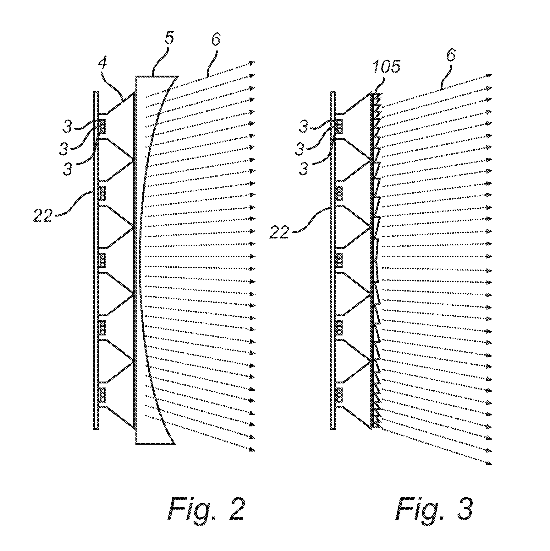
[0025]FIG. 2 shows a schematic view of a lamp with a negative lens 5. A number of light emitting elements 3 may e.g. be mounted on a Printed Circuit Board (PCB) layer 22. The PCB may e.g. comprise an isolated carrier made of a heat tra...


PUM


Abstract

A lighting system comprising a plurality of controllable light emitting elements 3 is disclosed. The lighting system further comprising a spreading optical element 5 arranged in front of the plurality of light emitting elements to shape the light emitted from the lighting elements, and a controller 7 for varying a light emission angle range of light emitted from the spreading optical element 5 by controlling each of the plurality of controllable light emitting elements. This allows the light emitted from the spreading optical element to be varied without varying any physical parts of the lighting system, because the controller now controls each of the light emitting elements, by e.g. dimming one or more of the light emitting elements or by switching one or more of the light emitting elements off.

Description

FIELD OF THE INVENTION[0001]The present invention relates to a controllable lighting system.BACKGROUND OF THE INVENTION[0002]Lighting systems are widely used to create ambiance in homes. The systems create light patterns that create atmospheres.[0003]WO 2009 / 031103 describes a multi color light source emitting light beams of different colors. The multi color light sources can be used in applications in which highly concentrated full spectrum light is required. Examples of such applications are spot lighting and digital projection. In this way the color of e.g. the spot lighting can be varied. But a problem with this arrangement is that in order to achieve a moving light pattern the light source needs to be moved by e.g. a mechanical arrangement. As a consequence of that, such systems are often not thin and compact but relatively thick and bulky.SUMMARY OF THE INVENTION[0004]It is an object of the present invention to overcome these problems, and to provide a lighting system that can...

Claims


Application Information

Patent Timeline
Patent Type & Authority Patents(United States)
IPC IPC(8): F21V11/00F21V5/00F21V5/04F21V23/04F21Y101/02F21Y105/00H05B44/00
CPCH05B33/0803F21V5/04F21Y2101/02F21V5/002F21Y2105/001F21V23/0464F21V29/504F21Y2105/10F21Y2115/10F21Y2113/13F21S10/00F21V23/04H05B45/22H05B47/19F21V5/005H05B45/20H05B45/10H05B45/325H05B45/00F21V5/048F21V23/0457
Inventor SNIJDER, PIETER JACOBBERKVENS, WINFRIED ANTONIUS HENRICUSCORNELISSEN, HUGO JOHANSONNEVILLE, PIERRE ROBERT VALERE
Owner SIGNIFY HLDG BV
Why Eureka
Try Eureka